S3C
Double Side Break Disconnector up to 300 kV
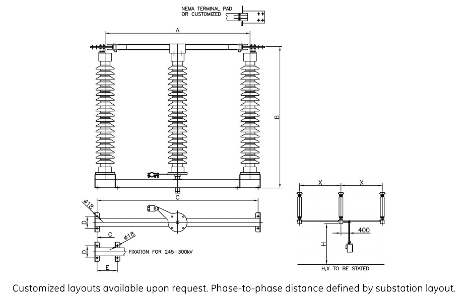
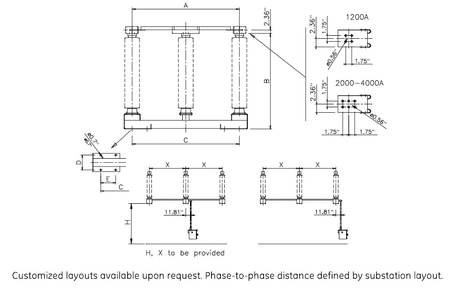
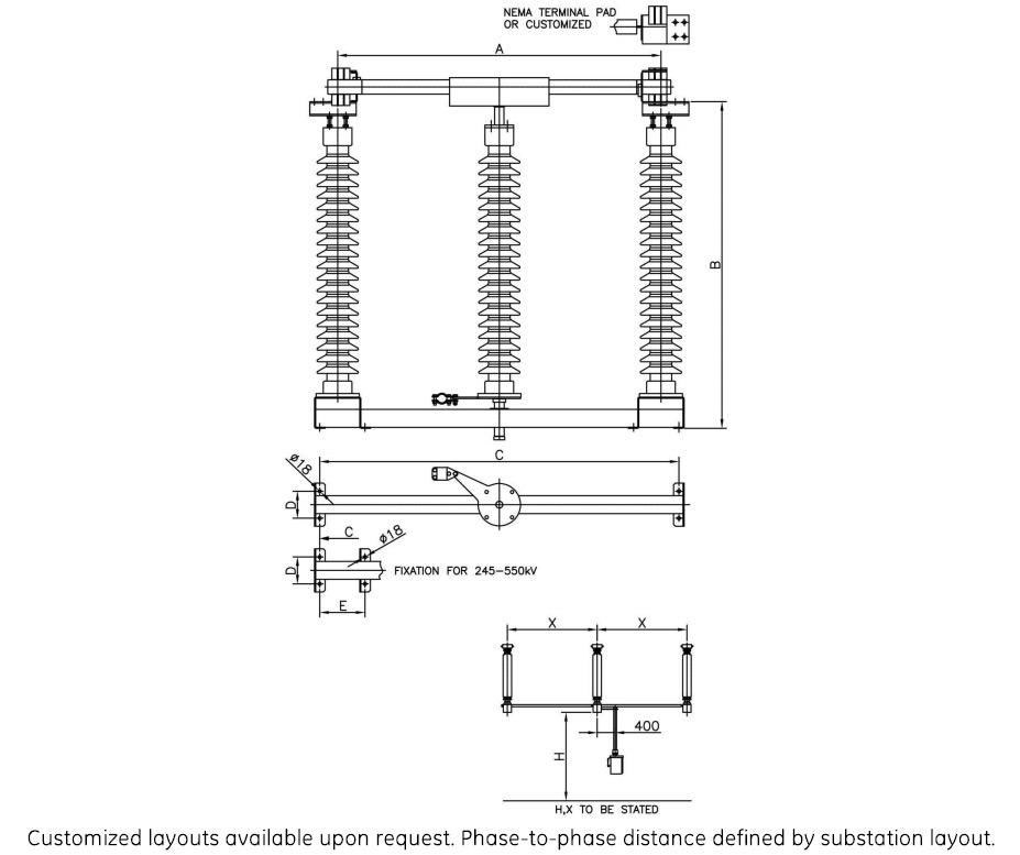
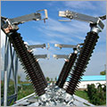
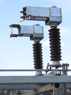
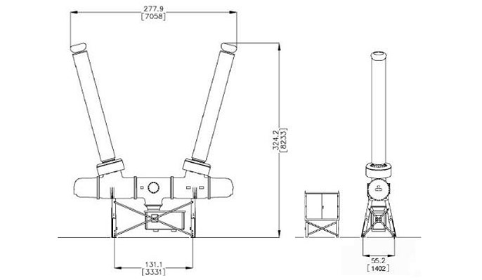
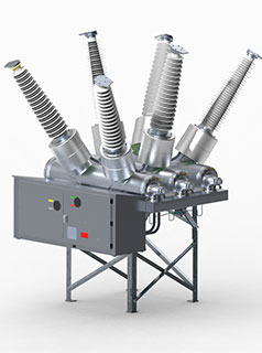
The S3C is a low profile, reduced phase-to-phase distance double side disconnector that provides additional space savings. The optimum mechanical and electrical characteristics of the current carrying parts are ensured through the use of high strength aluminium alloys combined with silver-plated copper contacts. The S3C can be customized for vertical, underhung and phase-over-phase installations.
S3C
Double Side Break Disconnector up to 300 kV
The S3C is a low profile, reduced phase-to-phase distance double side disconnector that provides additional space savings. The optimum mechanical and electrical characteristics of the current carrying parts are ensured through the use of high strength aluminium alloys combined with silver-plated copper contacts. The S3C can be customized for vertical, underhung and phase-over-phase installations.
- The optimum mechanical and electrical characteristics of the current carrying parts are ensured through the use of high strength aluminium alloys combined with silver-plated copper contacts
- Rectangular aluminum blade is attached to the top of the center rotating insulator and moves smoothly in the jaw
- Galvanized structural steel channel base supports the insulators and live parts, providing high strength and rigid design
- Center insulator stack rotates on weather sealed, greaseless rotor bearings
- Customizable for vertical, underhung and phase-over-phase installations
- Virtually maintenance free with factory-sealed bearings, life-time greased or self-lubricating parts and corrosion-free materials
Specifications
Technical Data (IEC)
| Rated Voltage | Rated Current A/ Short time current kA** | BIL kV | A mm | B mm | C mm | D mm | E mm |
|---|---|---|---|---|---|---|---|
| 72.5 kV | 3150/50 | 325 | 1100 | 1004 | 1200 | 130 | |
| 100 kV | 3150/50 | 450 | 1500 | 1276 | 1200 | 100 | |
| 123 kV | 3150/50 | 550 | 1500 | 1476 | 1200 | 150 | |
| 145 kV | 4000/63 | 650 | 1800 | 1757 | 200 | 150 | |
| 170 kV | 4000/63 | 750 | 2000 | 1979 | 2200 | 170 | |
| 245R kV | 4000/63 | 950 | 2400 | 2413 | 2600 | 220 | 270 |
| 245 kV | 4000/63 | 1050 | 2800 | 2613 | 3000 | 220 | 270 |
| 300 kV | 3150/50 | 1050 | 3200 | 2963 | 3400 | 220 | 270 |
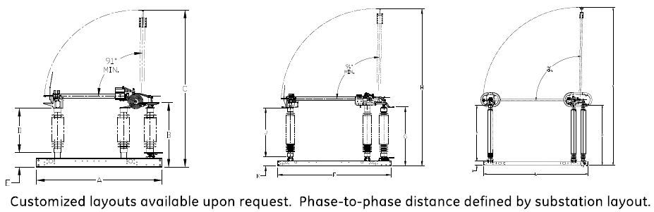
Drawings
S3CD
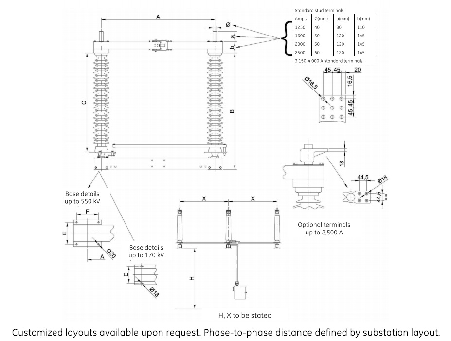
Double Side Break Disconnector up to 550 kV
The S3CD is a double side break disconnector on which the center insulator rotates to open and close the switch. It is particularly suited for applications in which low vertical clearance prohibits the use of other disconnectors. The S3CD is a rugged performer in adverse operating conditions and is always stable in the close position during short circuits.
S3CD
Double Side Break Disconnector up to 550 kV
The S3CD is a double side break disconnector on which the center insulator rotates to open and close the switch. It is particularly suited for applications in which low vertical clearance prohibits the use of other disconnectors. The S3CD is a rugged performer in adverse operating conditions and is always stable in the close position during short circuits.
- Rugged performer in adverse conditions such as high winds and heavy ice, and is stable in the close position during short circuits
- Particularly suited for applications in which low vertical clearance prohibits the use of other disconnectors
- Blades are extra heavy, one piece, tubular aluminium with replaceable silver plated copper contacts at each end
- Galvanized structural steel channel base supports the insulators and live parts, providing high strength and rigid design
- Center insulator stack rotates on weather sealed, greaseless rotor bearings
Specifications
Technical Data (IEC)
| Rated Voltage | Rated Current A/ Short time current kA** | BIL kV | A mm | B mm | C mm | D mm | E mm |
|---|---|---|---|---|---|---|---|
| 145 kV | 3150/63 A | 650 | 1800 | 1816 | 2000 | 150 | |
| 170 kV | 3150/63 A | 750 | 2000 | 2038 | 2200 | 170 | |
| 245R kV | 3150/63 A | 950 | 2400 | 2472 | 2600 | 220 | 270 |
| 245 kV | 3150/63 A | 1050 | 2800 | 2672 | 3000 | 220 | 270 |
| 300 kV | 3150/63 A | 1050 | 3200 | 3022 | 3400 | 220 | 270 |
| 362 kV | 3150/63 A | 1175 | 3800 | 3338 | 4050 | 270 | 340 |
| 420 kV | 3150/63 A | 1425 | 4200 | 3788 | 4450 | 270 | 340 |
| 550 kV | 3150/63 A | 1550 | 5000 | 4463 | 5250 | 270 | 340 |
Drawings
S2DA
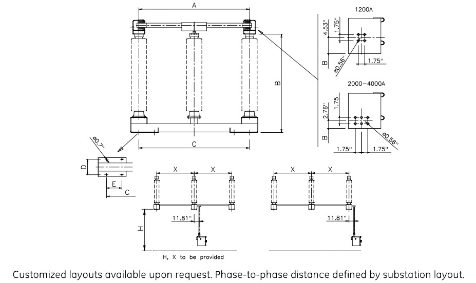
S2DA Center break disconnector up to 550 kV
The S2DA is reliable in high winds and heavy ice and always stable in the closed position during short circuits. A galvanised structural steel channel base supports the insulators and live parts, assuring a high strength, rigid design. The two insulator stacks rotate on weather-sealed, greaseless, maintenance-free rotor bearings and the blades are made of extra-heavy extruded aluminium with replaceable silver-plated copper contacts in the opening point.
S2DA
S2DA Center break disconnector up to 550 kV
The S2DA is reliable in high winds and heavy ice and always stable in the closed position during short circuits. A galvanised structural steel channel base supports the insulators and live parts, assuring a high strength, rigid design. The two insulator stacks rotate on weather-sealed, greaseless, maintenance-free rotor bearings and the blades are made of extra-heavy extruded aluminium with replaceable silver-plated copper contacts in the opening point.
- Rated voltage from 72,5 to 550kV
- Reliable in adverse operating conditions such as high winds and heavy ice
- Always stable in the close position during short circuits
- Flex technology for inspection free, long term operation (no need for sliding or rotary contacts)
- Supplied or easily retro-fitted with 1 or 2 earthing switches
- Customised solutions available: parallel, in-line, diagonal, vertical, underhung, phase-to-phase
Specifications
Technical Data (IEC)
| Rated Voltage | Rated Current A/ Short time current kA | BIL kV | A mm | B mm | C mm | ExF mm |
|---|---|---|---|---|---|---|
| 72.5 kV | 3,150/63 | 325 | 1,000 | 960 | 770 | 150 |
| 100 kV | 4,000/63 | 420 | 1,400 | 1,240 | 1,020 | 210 |
| 123 kV | 4,000/63 | 550 | 1,400 | 1,440 | 1,220 | 210 |
| 145 kV | 4,000/63 | 650 | 1,600 | 1,720 | 1,500 | 210 |
| 170 kV | 4,000/63 | 750 | 1,900 | 1,920 | 1,700 | 210 |
| 245R kV | 4,000/63 | 950 | 2,500 | 2,375 | 2,100 | 300x150 |
| 245 kV | 4,000/63 | 1,050 | 2,500 | 2,575 | 2,300 | 300x150 |
| 300 kV | 4,000/63 | 1,050, | 3,000 | 2,925 | 2,650 | 300x150 |
| 362 kV | 4,000/63 | 1,175 | 3,500 | 3,300 | ,2,900 | 270x270 |
| 420 kV | 4,000/63 | 1,425 | 4,200 | 3,750 | 3,350 | 270x270 |
| 550 kV | 4,000/63 | 1,550 | 4,700 | 4,400 | 4,000 | 270x270 |
Drawings
CGVB-08
Vertical Break Disconnector up to 345 kV
The CGVB-08 vertical break disconnector is available in a wide range of ratings and is a robust and reliable performer. The double jaw contact system provides low maintenance, long life and excellent electrical and mechanical performance in the most adverse operating conditions. The CGVB-08 can be customized for different layouts to meet specific project needs.
- Up to 4000 A
- Up to 80 kA/3 s
- Temperatures from -50°C to +50°C
- Ice up to 20 MM (3/4”)
- Virtually maintenance free with factory-sealed bearings, life-time greased or self-lubricating parts and corrosion-free materials
Optionnal Devices
The CGVB-08 can be fitted with integrated grounding switches, mounted either parallel or perpendicular to the disconnect switch blade travel. In addition, it can be fitted to a wide range of accessories including high speed whips, silver inlaid contact, interlocking mechanisms and auxiliary contacts.
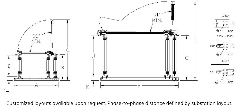
Specifications
25 to 245 kV 1200-2000 AMP
| Rated Voltage | Max. rated current | Short circuit current | BIL | A inch(mm) | B inch(mm) | C inch(mm) | D inch(mm) | E inch(mm) |
|---|---|---|---|---|---|---|---|---|
| 25.8 kV | 1200-2000 A | 38 kA 3 sec - 63 kA 3 sec | 150 | 59 (1499) | 26 (656) | 63 (1603) | 14 (356) | 10 (254) |
| 38 kV | 1200-2000 A | 38 kA 3 sec - 63 kA 3 sec | 200 | 69 (1753) | 30 (757) | 77 (1958) | 18 (457) | 10 (254) |
| 72.5 kV | 1200-2000 A | 38 kA 3 sec - 63 kA 3 sec | 350 | 85 (2165) | 42 (1062) | 103 (2619) | 30 (762) | 10 (254) |
| 121 kV | 1200-2000 A | 38 kA 3 sec - 63 kA 3 sec | 550 | 102 (2597) | 57 (1441) | 135 (3430) | 45 (1143) | 10 (254) |
| 145 kV | 1200-2000 A | 38 kA 3 sec - 63 kA 3 sec | 660 | 113 (2876) | 66 (1670) | 155 (3938) | 54 (1372) | 10 (254) |
| 169 kV | 1200-2000 A | 38 kA 3 sec - 63 kA 3 sec | 750 | 122 (3105) | 74 (1873) | 172 (4370) | 62 (1575) | 10 (254) |
| 242 kV | 1200-2000 A | 38 kA 3 sec - 63 kA 3 sec | 900 | 147 (3734) | 93 (2364) | 218 (5527) | 80 (2032) | 11 (286) |
| 242 kV | 1200-2000 A | 38 kA 3 sec - 63 kA 3 sec | 1000 | 163 (4140) | 105 (2668) | 246 (6238) | 92 (2337) | 11 (286) |
25 to 245 kV 3000-4000 AMP
| Rated Voltage | Max. rated current | Short circuit current | BIL | F inch(mm) | G inch(mm) | H inch(mm) | J inch(mm) | K inch(mm) |
|---|---|---|---|---|---|---|---|---|
| 25.8 kV | 4000 A | 80 kA 3 sec | 150 | 75 (1911) | 24 (621) | 87 (2211) | 15 (381) | 10 (254) |
| 38 kV | 4000 A | 80 kA 3 sec | 200 | 84 (2125) | 29 (730) | 101 (2556) | 18 (457) | 10 (254) |
| 72.5 kV | 4000 A | 80 kA 3 sec | 350 | 95 (2410) | 39 (1002) | 122 (3099) | 30 (762) | 10 (254) |
| 121 kV | 4000 A | 80 kA 3 sec | 550 | 113 (2877) | 54 (1383) | 160 (3937) | 45 (1143) | 10 (254) |
| 145 kV | 4000 A | 80 kA 3 sec | 650 | 124 (3156) | 63 (1611) | 175 (4445) | 54 (1372) | 10 (254) |
| 169 kV | 4000 A | 80 kA 3 sec | 750 | 131 (3334) | 71 (1814) | 190 (4826) | 62 (1575) | 10 (254) |
| 242 kV | 4000 A | 80 kA 3 sec | 900 | 135 (4172) | 89 (2272) | 243 (6153) | 80 (2032) | 10 (254) |
| 242 kV | 4000 A | 80 kA 3 sec | 1050 | 184 (4680) | 101 (2576) | 274 (6966) | 92 (2337) | 10 (254) |
| 362 kV | 1200-4000 A | 80 kA 3 sec | 1300 | 199 (5042) | 115 (2910) | 303 (7706) | 106 (2692) | 9 (230) |
Drawings
Recommended Products & services
S3CVS Vertical Break Disconnectors up to 72 kV
The S3CVS is a heavy duty vertical break disconnector suitable for high current...
View More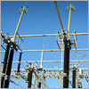
S3CVL Vertical Break Disconnectors up to 550 kV
The S3CVL, rated from 245 to 550 kV, is a modern, 3 insulator vertical break disconnector...
View More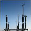
S3CV Vertical Break Disconnectors up to 245 kV
GE Vernovaâs S3CV vertical break disconnector is rated from 52 to 245 kV. Rigid and...
View MoreCGVB-05
Vertical Break Disconnector up to 550 kV
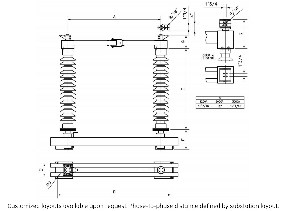
GE Vernova’s CGVB-05 vertical break disconnector is designed to reduce phase spacing to a minimum. The jaw end of the switch is supported by one fixed insulator. The hinge end consists of two insulators, one fixed, the other rotates to open and close the switch. The double movement of the aluminum blade ensures high short circuit rating and excellent ice breaking capabilities. The CGVB-05 is designed to be maintenance free with factory sealed bearing housings and counter balancing springs.
CGVB-05
Vertical Break Disconnector up to 550 kV
GE Vernova’s CGVB-05 vertical break disconnector is designed to reduce phase spacing to a minimum. The jaw end of the switch is supported by one fixed insulator. The hinge end consists of two insulators, one fixed, the other rotates to open and close the switch. The double movement of the aluminum blade ensures high short circuit rating and excellent ice breaking capabilities. The CGVB-05 is designed to be maintenance free with factory sealed bearing housings and counter balancing springs.
- Temperatures from -50°C to +50°C
- Ice up to 20 MM (3/4”)
- Hinge current transfer by laminated shunts up to 2000 A and double jaw for 3000 A and 4000 A
- Silver-to-silver, field-replaceable contacts
- Jacking bolts for insulator adjustments
- Swing handle, handcrank or motor operation
- Provision for padlocking
- Visual position indicator
- Arcing horns
- High-speed whip
- Vacuum interrupter
- Auxiliary contacts
- Interlock mechanisms
- Build-on ground switch
- Factory mounted insulators up to 245 kV
Specifications
25 to 245 kV 1200-2000 A
| Rated Voltage | Max. rated current | Short circuit current | BIL | A inch(mm) | B inch(mm) | C inch(mm) | D inch(mm) | E inch(mm) |
|---|---|---|---|---|---|---|---|---|
| 25.8 kV | 1200-2000 A | 38 kA 3 sec - 63 kA 3 sec | 150 | 59 (1499) | 28 (710) | 66 (1690) | 14 (355) | 10 (254) |
| 38 kV | 1200-2000 A | 38 kA 3 sec - 63 kA 3 sec | 200 | 69 (1753) | 32 (810) | 76 (1950) | 18 (457) | 10 (254) |
| 72.5 kV | 1200-2000 A | 38 kA 3 sec - 63 kA 3 sec | 350 | 85 (2159) | 44 (1115) | 106 (2699) | 30 (760) | 10 (254) |
| 121 kV | 1200-2000 A | 38 kA 3 sec - 63 kA 3 sec | 550 | 102 (2597) | 59 (1494) | 139 (3527) | 45 (1143) | 10 (254) |
| 145 kV | 1200-2000 A | 38 kA 3 sec - 63 kA 3 sec | 660 | 113 (2870) | 68 (1725) | 157 (4000) | 54 (1370) | 10 (254) |
| 169 kV | 1200-2000 A | 38 kA 3 sec - 63 kA 3 sec | 750 | 124 (3150) | 76 (1930) | 178 (4520) | 62 (1575) | 10 (254) |
| 242 kV | 1200-2000 A | 38 kA 3 sec - 63 kA 3 sec | 900 | 147 (3734) | 95 (2416) | 223 (5659) | 80 (2032) | 11 (286) |
| 242 kV | 1200-2000 A | 38 kA 3 sec - 63 kA 3 sec | 1000 | 169 (4140) | 107 (2700) | 251 (6374) | 92 (2340) | 11 (286) |
25 to 245 kV 3000-4000 A
| Rated Voltage | Max. rated current | Short circuit current | BIL | F inch(mm) | G inch(mm) | H inch(mm) | J inch(mm) | K inch(mm) |
|---|---|---|---|---|---|---|---|---|
| 25.8 kV | 3000-4000 A | 38 kA 3 sec - 63 kA 3 sec | 150 | 73 (1854) | 25 (632) | 83 (2118) | 14 (356) | 10 (254) |
| 38 kV | 3000-4000 A | 38 kA 3 sec - 63 kA 3 sec | 200 | 85 (2159) | 29 (735) | 97 (2462) | 18 (457) | 10 (254) |
| 72.5 kV | 3000-4000 A | 38 kA 3 sec - 63 kA 3 sec | 350 | 95 (2413) | 41 (1037) | 118 (3010) | 30 (762) | 10 (254) |
| 121 kV | 3000-4000 A | 38 kA 3 sec - 63 kA 3 sec | 550 | 113 (2877) | 56 (1419) | 152 (3873) | 45 (1143) | 10 (254) |
| 145 kV | 3000-4000 A | 38 kA 3 sec - 63 kA 3 sec | 660 | 124 (3150) | 66 (1680) | 173 (4394) | 54 (1375) | 10 (254) |
| 169 kV | 3000-4000 A | 38 kA 3 sec - 63 kA 3 sec | 750 | 131 (3327) | 73 (1851) | 187 (4742) | 62 (1575) | 10 (254) |
| 242 kV | 3000-4000 A | 38 kA 3 sec - 63 kA 3 sec | 900 | 183 (4648) | 104 (2646) | 273 (6944) | 92 (2340) | 11 (286) |
362 to 550 kV 3000-4000 A
| Rated Voltage | Max. rated current | Short circuit current | BIL | L inch(mm) | M inch(mm) | N inch(mm) | P inch(mm) | Q inch(mm) |
|---|---|---|---|---|---|---|---|---|
| 362 kV | 3000-4000 A | 63 kA 3 sec - 80 kA 3 sec | 1300 | 198 (5029) | 116 (2946) | 303 (7696) | 106 (2692) | 9 (225) |
| 550 kV | 3000-4000 A | 63 kA 3 sec - 80 kA 3 sec | 1550 | 246 (6248) | 143 (3630) | 384 (9766) | 128 (3251) | 9 (225) |
| 550 kV | 3000-4000 A | 63 kA 3 sec - 80 kA 3 sec | 1800 | 270 (6858) | 162 (4110) | 427 (10854) | 152 (3861) | 9 (225) |
Drawings
Recommended Products & services
S3CVS Vertical Break Disconnectors up to 72 kV
The S3CVS is a heavy duty vertical break disconnector suitable for high current...
View More
S3CVL Vertical Break Disconnectors up to 550 kV
The S3CVL, rated from 245 to 550 kV, is a modern, 3 insulator vertical break disconnector...
View More
S3CV Vertical Break Disconnectors up to 245 kV
GE Vernovaâs S3CV vertical break disconnector is rated from 52 to 245 kV. Rigid and...
View MoreDT2-550
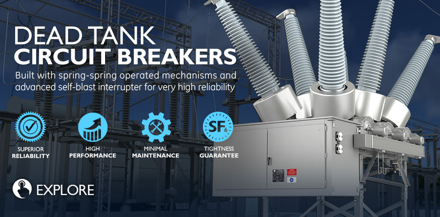
Dead Tank Circuit Breaker for 550 kV
Proven and robust solution
The DT2-550 is ideal for applications at 550 kV levels and below, including 420 kV transmission systems. It is specifically designed and tested for general or definite purpose applications and for severe environmental conditions, including low temperatures, highly active seismic areas, regions with high pollution levels and corrosive atmospheres.
DT2-550
Dead Tank Circuit Breaker for 550 kV
Proven and robust solution
The DT2-550 is ideal for applications at 550 kV levels and below, including 420 kV transmission systems. It is specifically designed and tested for general or definite purpose applications and for severe environmental conditions, including low temperatures, highly active seismic areas, regions with high pollution levels and corrosive atmospheres.
High Performance
The DT2-550 is suitable for applications up to nameplate ratings, including definite purpose ratings for capacitor bank switching. Extensive mechanical operation design testing (in excess of 10,000 operation), assures trouble-free operation for the lifetime of the circuit breaker. Intensive production leak testing assures superior in-service SF₆ performance. All external surfaces are corrosion resistant, without the need for maintenance-intensive paint.
Flexibility
The DT2-550 is available with design options and ratings to best fit your needs. Designed with a footprint that minimizes foundation costs, the DT2-550 adapts to retrofit live tank or dead tank foundations.
Synchronized Switching
The DT2-550 is an independent pole operation (IPO) circuit breaker provided with one mechanism per pole. The DT2-500 circuit breaker can be supplied with the Point on Wave controller for synchronous closing in capacitor bank and line switching applications, or synchronous opening in reactor switching applications.
Flexible Options
The DT2-550 is available with design options and ratings to best fit your needs. Designed with a footprint that minimizes foundation costs, the DT2-550 adapts to retrofit live tank or dead tank foundations.
The DT2-550 can be provided with reliable spring-operated mechanisms for 2.5 cycle operation or a compact, low-pressure hydraulic mechanism for 2 cycle operation.
The DT2-550 can also be supplied with many customized options such as closing resistors, electronic density monitors and composite bushings. The generous enclosure allows space for up to three current transformers per bushing to accommodate complex measurement and protection schemes.
Installation
The DT2-550 is factory tested, adjusted and prepared for shipment with the bushings disassembled. On-site installation requires only a few simple steps. Thanks to the low energy spring mechanisms and low pressure hydraulic mechanisms, the DT2-550 is considered virtually maintenance free.
Specifications
| IEEE/ANSI | IEC | Value | Units |
|---|---|---|---|
| Rated maximum voltage | Rated voltage | 550 | kV |
| Rated power frequency | Rated frequency | 50/60 | Hz |
| Dry withstand | At power frequency,dry | 860 | kV |
| Rated lightning impulse withstand voltage | At lightning impulse | 1,800 | kV |
| Rated chopped wave impulse voltage 2us | 2,070 | kV | |
| Rated switching impulse withstand voltage terminal to terminal | Rated switching impulse withstand voltage terminal to terminal | 1,300 | kV |
| Rated continuous current | Rated normal current | 3,000/4,000/5,000 | A |
| Rated short-circuit current | Rated short-circuit breaking current | 40/50/60 | kA |
| Rated closing,latching and short time carrying | 164 | kA | |
| Rated short-circuit making current | 163 | kA | |
| Rated capacitance switching* | |||
| Rated break time (spring/hydraulic) | 500 | A | |
| Rated interrupting time (spring/hydraulic) | 2.5/2.0 | cycles | |
| Rated break time (spring/hydraulic) | 42/33 | ms | |
| Rated standard operating duty | O-CO-15s-CO O-0.3s-CO-180s-CO | ||
| *Rating available upoon request. **Please contact Grid Solutions for special purpose, high TRV, high X/R or other ratings requirements | |||
Drawings
Recommended Products & services
DT1-145g 63
Leading SFâ-free Breaker with 63 kA Short-Circuit Current The SFâ-free DT1-145g rated...
View More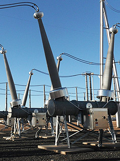
Dead Tank Circuit Breakers
Grid Solutions, a GE Vernova business, offers a comprehensive range of dead tank circuit...
View More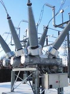
DT1-362
State-of-the-Art Technology GE Vernovaâs DT series of dead tank circuit breakers are...
View MoreDT1-362
Dead Tank Circuit Breaker for 362 kV
State-of-the-Art Technology
GE Vernova’s DT series of dead tank circuit breakers are characterized by advanced self-blast interrupters, leak-resistant, cast aluminum enclosures and durable, low-energy spring-spring-operated mechanisms. More than 100,000 circuit breakers with self-blast interrupters and FK spring-spring-operated mechanisms have been in service since 1989.
DT1-362
Dead Tank Circuit Breaker for 362 kV
State-of-the-Art Technology
GE Vernova’s DT series of dead tank circuit breakers are characterized by advanced self-blast interrupters, leak-resistant, cast aluminum enclosures and durable, low-energy spring-spring-operated mechanisms. More than 100,000 circuit breakers with self-blast interrupters and FK spring-spring-operated mechanisms have been in service since 1989.
Transportation
The circuit breaker design is optimized for quick and easy installation at site. Where truck shipments are possible, individual poles are shipped with bushings and the operating mechanism assembled. In this case, site work involves installing the poles on the supporting frame and making the necessary low voltage electrical connections. Each phase is factory set to the proper position, eliminating the need for complex rigging at site.
Leading Gas Testing
Every DT1-362 breaker produced by GE Vernova is subjected to a rigorous SF6 tightness testing protocol. Our state-of-the-art testing system validates the gas integrity of every circuit breaker in the as shipped condition. This proprietary system provides quantifiable evidence of our <0.5% guaranteed leak rate in the exact configuration in which the breaker is delivered.
Certified Quality
The DT1-362 is suitable for applications up to nameplate ratings, including definite purpose ratings and is uniquely qualified under the latest ANSI IEC standards as C2 class for capacitance switching including back-to-back (very low restrike probability) and for reactor switching applications. Extensive mechanical operation design testing ensures trouble-free operation for the lifetime of the circuit breaker. Intensive production leak testing ensures superior in-service SF6 performance.
GE Vernova designs, manufactures, tests and delivers its circuit breakers in accordance with the latest IEEE/ANSI and IEC standards, maintaining a quality assurance system according to ISO-9011 and ISO-14001 certifications. The center of excellence for dead tank circuit breakers is located in Charleroi, PA (USA).
Specifications
| IEEE/ANSI | IEC | Value | Units |
|---|---|---|---|
| Rated maximum voltage* | Rated voltage* | 362 | kV |
| Rated power frequency | Rated frequency | 50/60 | Hz |
| Rated dielectric withstand capability: - dry withstand | Rated insulation level - at power frequency,dry | 555 | kV |
| Rated lightning impulse withstand voltage | - at lightning impulse | 1,300 | kV |
| Rated chopped wave impulse voltage 2us | 1,680 | kV | |
| Rated switching impulse | 900 | kV | |
| Rated continuous current | Rated normal current | 3,000/4,000/5,000 | A |
| Rated short-circuit current | Rated short-circuit breaking current | 40/50/63 | kA |
| Rated closing,latching and short time carrying | 170 | kA | |
| Rated short-circuit making current | 170 | kA | |
| Rated capacitance switching* | 500 | A | |
| Rated single capacitor bank breaking current | 500 | A | |
| Rated interrupting time | 2 | cycles | |
| Rated break time | 33 | ms | |
| Rated standard operating duty | Rated operating sequence | O-CO-15s-CO O-0.3s-CO-180s-CO | |
| *Rating available upoon request **Contact GE Vernova for special purpose, operating voltage, generator synchronizing,high TRV, high X/R or other ratings requirements. | |||
Drawings
Recommended Products & services
DT1-145g 63
Leading SFâ-free Breaker with 63 kA Short-Circuit Current The SFâ-free DT1-145g rated...
View More
Dead Tank Circuit Breakers
Grid Solutions, a GE Vernova business, offers a comprehensive range of dead tank circuit...
View More
DT1-362
State-of-the-Art Technology GE Vernovaâs DT series of dead tank circuit breakers are...
View MoreDT1-245P 63
Dead Tank Circuit Breaker for 245 kV / 63 kA
State-of-the-Art Technology
GE Vernova’s DT series of dead tank circuit breakers are characterized by advanced self-blast interrupters, leak-resistant, cast aluminum single piece enclosures and durable, low-energy spring-operated mechanisms. More than 120,000 circuit breakers with self-blast interrupters and FK spring-operated mechanisms have been in service since 1989.
DT1-245P 63
Dead Tank Circuit Breaker for 245 kV / 63 kA
State-of-the-Art Technology
GE Vernova’s DT series of dead tank circuit breakers are characterized by advanced self-blast interrupters, leak-resistant, cast aluminum single piece enclosures and durable, low-energy spring-operated mechanisms. More than 120,000 circuit breakers with self-blast interrupters and FK spring-operated mechanisms have been in service since 1989.
Spring-Spring-Operated Mechanism
The reduced energy requirements within the breaking chamber allows for the utilization of GE Vernova’s world class FK spring-spring mechanism. The combination of the proven FK drive mechanism and interrupter technology results in a significant reduction of reaction forces, thereby reducing foundation design requirements.
SF6-Gas Tightness Guarantee
GE Vernova is a leader in the industry in SF6 gas tightness testing technology including seals, castings, and plumbing systems. Each breaker is factory tested using GE Vernova’s proprietary gas tightness testing system which provides measurable, quantifiable test results on the breaker in its fully assembled, as-shipped condition.
Certified Quality
GE Vernova designs, manufactures, tests and delivers its circuit breakers in accordance with the latest IEEE/ANSI and IEC standards, maintaining a quality assurance system according to ISO 9011 and ISO 14001 certifications.
Superior Manufacturing & Domestic Content
The center of excellence for dead tank circuit breakers is located in Charleroi, PA (USA), where dead tank circuit breakers up to 550 kV and live tank circuit breakers up to 800 kV are assembled. The production lines feature high degree of domestic content, which can help to facilitate compliance with national requirements. In addition, the complete wiring and assembling of low voltage control cabinets and mechanism cabinets is done locally, resulting in greater flexibility to respond to utility needs.
Simplified Installation and Maintenance
The DT1-245P 63 model is factory tested and prepared for shipment with bushings assembled and pre-filled with SF6 gas. As a result, the on-site installation requires only a few simple steps without requiring any special tools. The DT1-245P 63 circuit breaker range has lower maintenance costs and requirements owing to an engineering and design philosophy that has focused on these key needs since the inception of the development process.
Specifications
| IEEE/ANSI | IEC | Value | Units |
|---|---|---|---|
| Rated maximum voltage | Rated Voltage | 245 | kV |
| Rated power frequency | Rated frequency | 60/50 | Hz |
| Dry withstand | At power frequency dry | 425/460 | kV |
| Rated Lighning impulse withstand voltage | At lighting impulse | 900/1,050 | kV |
| Rated chopped wave impulse voltage 2 µs | 1,160 | kV | |
| Rated continuous current | Rated normal current | 3,000/4,000/5,000 | A |
| Rated short-circuit current | Rated short-circuit breaking current | 63 | kA |
| Rated closing, latching and short time carrying | 164 | kA | |
| Rated short-circuit making current | 164 | kA | |
| Rated capacitance switching* | |||
| Rated Interrupting time | 2/3 | cycles | |
| Rated break time | 33/50 | ms | |
| Rated standard operating duty | 0-0,3s-CO-15s-CO |
* Ratings available upon request. Contact GE Vernova for special purpose, high TRV, high X/R or other ratings requirements.
| Technical Data | Value | Units |
|---|---|---|
| Ambient temperature range* | -30 +40 | degree C |
| Seismic withstand in accordance with IEEE 693-2018 | ||
| Creepage distance | 168/4,257 | inches/mm |
| Closing resistor (optional)* | ||
| Weight (without current transformers) | 8,015/3,643 (GO) and 8,894/4,043 (IPO) | lbs/kg |
| Weight of SF6 | 143/65 | lbs/kg |
* Alternate values upon request
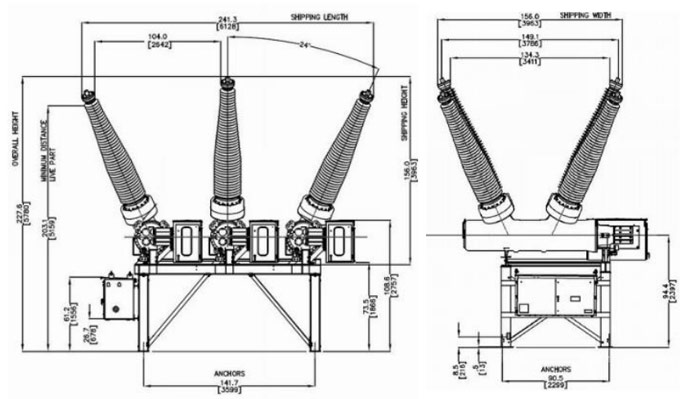
Drawings
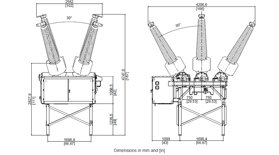 Three-pole gang operation
 Independent pole operation
Recommended Products & services
DT1-145g 63
Leading SFâ-free Breaker with 63 kA Short-Circuit Current The SFâ-free DT1-145g rated...
View More
Dead Tank Circuit Breakers
Grid Solutions, a GE Vernova business, offers a comprehensive range of dead tank circuit...
View More
DT1-362
State-of-the-Art Technology GE Vernovaâs DT series of dead tank circuit breakers are...
View MoreDT1-245P
Dead Tank Circuit Breaker for 245 kV
State-of-the-Art Technology
GE Vernova’s DT series of dead tank circuit breakers are characterized by advanced self-blast interrupters, leak-resistant, cast aluminum enclosures and durable, low-energy spring-operated mechanisms. More than 100,000 circuit breakers with self-blast interrupters and FK spring-operated mechanisms have been in service since 1989.
DT1-245P
Dead Tank Circuit Breaker for 245 kV
State-of-the-Art Technology
GE Vernova’s DT series of dead tank circuit breakers are characterized by advanced self-blast interrupters, leak-resistant, cast aluminum enclosures and durable, low-energy spring-operated mechanisms. More than 100,000 circuit breakers with self-blast interrupters and FK spring-operated mechanisms have been in service since 1989.
Spring-spring mechanism
The reduced energy requirements of the breaking chamber allows for the utilization of the world class FK spring-spring mechanism. The combination of the proven FK drive mechanism and interrupter technology results in a significant reduction of reaction forces, thus reducing foundation design requirements.
Gas Tightness Guarantee
GE Vernova leads the industry in SF6 gas tightness testing technology including seals, castings, and plumbing systems. Each breaker is factory tested using GE Vernova’s proprietary gas tightness testing system which provides measurable, quantifiable test results on the breaker in its fully assembled, as-shipped condition.
Certified Quality
GE Vernova designs, manufactures, tests and delivers its circuit breakers in accordance with the latest IEEE/ANSI and IEC standards, maintaining a quality assurance system according to ISO-9011 and ISO-14001 certifications. The center of excellence for dead tank circuit breakers is located in Charleroi, PA.
Installation and Maintenance
The DT1-245 series is factory tested and prepared for shipment with bushings assembled and prefilled with SF6 gas, therefore the on-site installation requires only a few simple steps without requiring any special tools. The DT1-245 circuit breaker range has lower maintenance costs and requirements, thanks to an engineering and design philosophy that has focused on these key needs since the inception of the development process.
Specifications
| IEEE/ANSI | IEC | Value | Units |
|---|---|---|---|
| Rated maximum voltage | Rated voltage | 245 | kV |
| Rated power frequency | Rated frequency | 50/60 | Hz |
| Dry withstand | At power frequency,dry | 425/460 | kV |
| Rated lightning impulse withstand voltage | At lightning impulse | 900/1,050 | kV |
| Rated chopped wave impulse voltage 2us | 1,160 | kV | |
| Rated continuous current | Rated normal current | 3,000/4,000 | A |
| Rated short-circuit current | Rated short-circuit breaking current | 40 | kA |
| Rated closing,latching and short time carrying | 104 | kA | |
| Rated short-circuit making current | 104 | kA | |
| Rated capacitance switching* | |||
| Rated interrupting time | 3 | cycles | |
| Rated break time | 50 | ms | |
| Rated standard operating duty | O-CO-15s-CO O-0.3s-CO-180s-CO | ||
| *Rating available upoon request **Contact Grid Solutions for special purpose, high TRV, high X/R or other ratings requirements. | |||
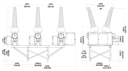
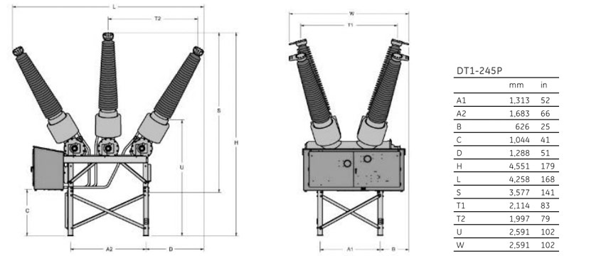
Drawings
Recommended Products & services
DT1-145g 63
Leading SFâ-free Breaker with 63 kA Short-Circuit Current The SFâ-free DT1-145g rated...
View More
Dead Tank Circuit Breakers
Grid Solutions, a GE Vernova business, offers a comprehensive range of dead tank circuit...
View More
DT1-362
State-of-the-Art Technology GE Vernovaâs DT series of dead tank circuit breakers are...
View MoreDT1-145R-40
Dead Tank Circuit Breaker with Pre-Insertion Resistors
State-of-the-Art Technology
The DT1-145R-40 is a dead tank circuit breaker furnished with integral pre-insertion resistors (PIRs). It may be used for switching of lines, transformers, shunt capacitors, or shunt reactors. It is specifically designed and tested for general or definite purpose applications as well as for severe environmental conditions including low temperatures, highly active seismic areas, and regions with high pollution levels or corrosive atmospheres.
DT1-145R-40
Dead Tank Circuit Breaker with Pre-Insertion Resistors
State-of-the-Art Technology
The DT1-145R-40 is a dead tank circuit breaker furnished with integral pre-insertion resistors (PIRs). It may be used for switching of lines, transformers, shunt capacitors, or shunt reactors. It is specifically designed and tested for general or definite purpose applications as well as for severe environmental conditions including low temperatures, highly active seismic areas, and regions with high pollution levels or corrosive atmospheres.
Gas Tightness Guarantee
Grid Solutions at GE Vernova leads the industry in SF6 gas tightness testing technology including seals, castings, and plumbing systems. Each breaker is factory tested using Grid Solutions at GE Vernova’s proprietary gas tightness testing system which provides measurable, quantifiable test results on the breaker in its fully assembled, as-shipped condition.
Quality
Grid Solutions at GE Vernova designs, manufactures, tests and delivers its circuit breakers in accordance with the latest IEEE/ANSI and IEC standards, maintaining a quality assurance system according to ISO-9011 and ISO-14001 certifications. The center of excellence for dead tank circuit breakers is located in Charleroi, PA.
Installation and Maintenance
The DT1-145R is factory tested and adjusted and don’t require any special tools for installation. Designed with the smallest symmetrical footprint to allow for minimized foundation costs, they are recognized worldwide as easy-to-install and operate circuit breakers. Thanks to the low energy mechanism and lifetime lubricants, the DT series is virtually maintenance free.
The DT1 series on-site installation requires only a few simple steps. For installations where truck shipment is impossible, all DT series circuit breakers can be readied for standard container shipment with only their bushings disassembled.
Pre-insertion Resistors (PIRs)
The circuit breaker random switching can generate voltage disturbances on electrical lines. Placed in parallel of the main contacts of a circuit breaker, a pre-insertion resistor is a technique consisting in operating the circuit-breaker while briefly inserting a resistor during closing operation to reduce overvoltage phenomena such as switching transient voltage. This helps limit the power quality issues and accelerated aging, thus minimizing risks and operation costs. Integral PIRs may be used for switching of lines, transformers, shunt capacitors or shunt reactors.
Ratings
| IEEE/ANSI | IEC | Value | Units |
|---|---|---|---|
| Rated maximum voltage* | Rated voltage | 72.5/123/145 | kV |
| Rated power frequency | Rated frequency | 50/60 | Hz |
| Rated dielectric withstand capability: - dry withstand - wet withstand | Rated insulation level - at power frequency, dry - at power frequency, wet | 160/260/310/365 140/230/275/315 | kV kV |
| Rated lightning impulse withstand voltage | - at lightning impulse | 350/550/650/750 | kV |
| Rated chopped wave impulse voltage 2us | 452/710/838/968 | kV | |
| Rated continuous current | Rated normal current | 1,200/2,000/3,000 | A |
| Rated short-circuit current | Rated short-circuit breaking current | 40 | kA |
| Rated short-time current (1s) | 63 | kA | |
| Rated peak withstand current | 164 | kA | |
| Rated capacitance switching* | Class C2 | ||
| Rated interrupting time | 3 | cycles | |
| Rated break time | 50 | ms | |
| Rated standard operating duty | Rated operating sequence | O-CO-15s-CO O-0.3s-CO-180s-CO | |
| *Standard values: further data is available on request. | |||
| **Please contact Grid Solutions for special purpose, high TRV, high X/R or other ratings requirements. | |||
Dimensions
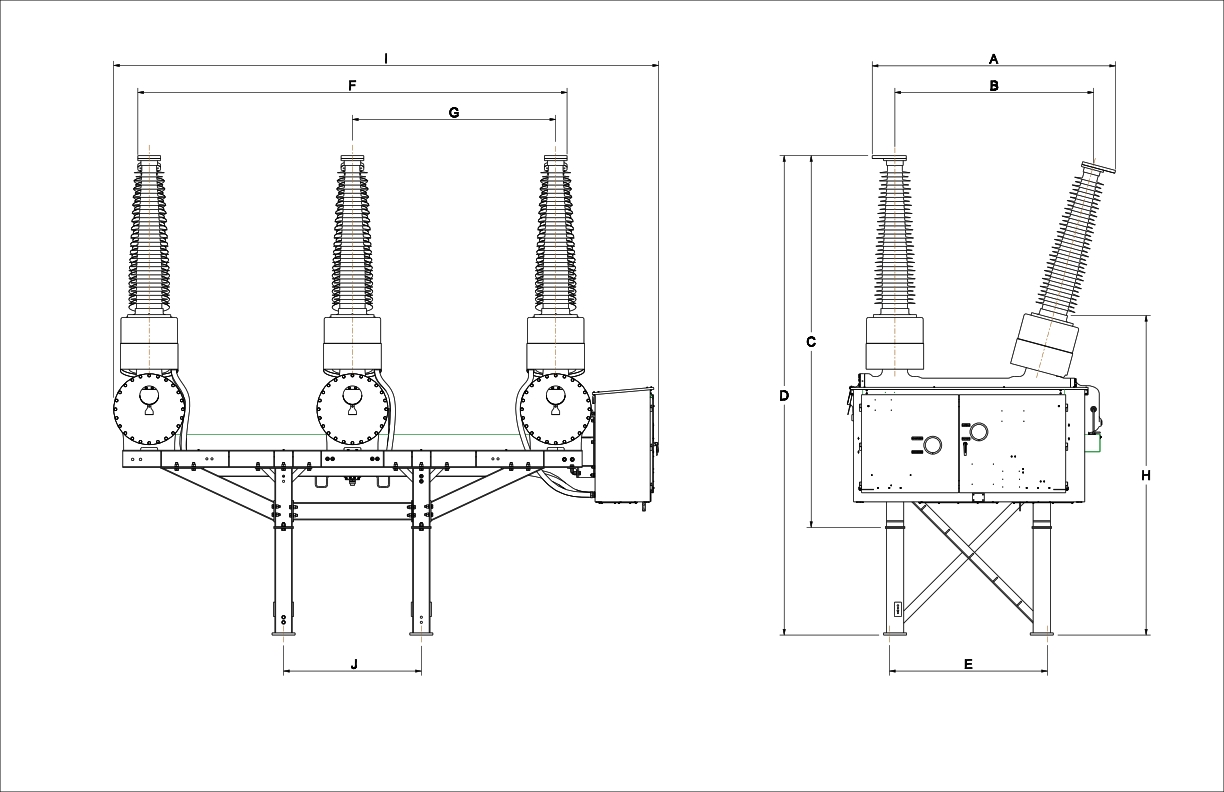
| Rated Max. Voltage | A (in/mm) | B (in/mm) | C (in/mm) | D (in/mm) | E (in/mm) | F (in/mm) | G (in/mm) | H (in/mm) | I (in/mm) | J (in/mm) |
|---|---|---|---|---|---|---|---|---|---|---|
| 72.5 kV | 79/1996 | 63/1597 | 105/2676 | 143/3624 | 55/1393 | 149/3777 | 71/1793 | 112/2857 | 189/4806 | 48/1215 |
| 145 kV | 84/2145 | 69/1752 | 129/3279 | 166/4228 | 55/1393 | 149/3785 | 71/1793 | 111/2819 | 189/4806 | 48/1215 |
Weight
(without current transformers)
| 72.5 kV: | 5,658/2572 | lb/kg |
| 145 kV: | 6,170/2,798 | lb/kg |
Recommended Products & services
DT1-145g 63
Leading SFâ-free Breaker with 63 kA Short-Circuit Current The SFâ-free DT1-145g rated...
View More
Dead Tank Circuit Breakers
Grid Solutions, a GE Vernova business, offers a comprehensive range of dead tank circuit...
View More
DT1-362
State-of-the-Art Technology GE Vernovaâs DT series of dead tank circuit breakers are...
View More