F35
Gas-Insulated Substations up to 170 kV
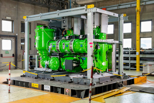
GE Vernova's F35 GIS is a field-proven solution with high availability that meets the challenges of networks up to 170 kV for power generation, transmission, distribution, tertiary and heavy industry applications. The F35 is available in 72.5 kV, 145 kV and 170 kV ratings. GE Vernova’s F35 is also available SF₆-free with g3-gas technology, see F35g
F35
Gas-Insulated Substations up to 170 kV
GE Vernova's F35 GIS is a field-proven solution with high availability that meets the challenges of networks up to 170 kV for power generation, transmission, distribution, tertiary and heavy industry applications. The F35 is available in 72.5 kV, 145 kV and 170 kV ratings. GE Vernova’s F35 is also available SF₆-free with g3-gas technology, see F35g
Main Characteristics
Environment friendliness
- Low gas weight
- Advanced SF₆ sealing system
- Smart grid features including full-digital monitoring, control and protection
- Available in g³ up to 145 kV
High availability
- One of the best experiences and high data reliability
- Current transformers outside SF₆
- Drives and accessories at easy reach
- Pure-spring circuit breaker drives
Low costs of land and civil works
- One of the most compact GIS with bay footprint up to 45% below market average depending on kV rating
- Up to 2 bays (145 kV), up to 3 bays (72.5 kV), and complete bays (170 kV) assembled, wired, tested and shipped
- Isolating device for voltage transformer / surge arrester
Applicable for wind turbines at 72.5 kV
- Handle more power while reducing energy losses
- A compact HV substation fits in the wind turbine
- Withstands harsh environments
- Short installation time
Specifications
| General ratings | |||
| Reference electrotechnical standards | IEC/IEEE/GB | IEC/IEEE/GB | IEC/IEEE |
| Voltages | 72.5 kV | 145 kV | 170 kV |
| Withstand voltages | |||
| - Short-duration power-frequency, phase-to-earth / across isolating distance | 140/160 kV | 275/315 kV | 325/375 kV |
| - Lightning impulse, phase-to-earth / across isolating distance | 325/375 kVp | 650/750 kVp | 750/860 kVp |
| Frequency | 50/60 Hz | 50/60 Hz | 50/60 Hz |
| Continuous current | up to 2500A | up to 3150A | up to 4000A |
| Short-time withstand current | 31.5 kA | 40 kA | 50 kA |
| Peak withstand current | 85 kAp | 100/108 kAp | 125/130 kAp |
| Duration of short-circuit | 3s | 3s | 3s |
| Installation | Indoor | Indoor/outdoor | Indoor |
| Ambient temperature range | down to -30 / up to +55 °C | down to -30 / up to +55 °C | down to -25 / up to +55 °C |
| Circuit-breaker ratings | |||
| First-pole-to-clear factor | 1.5 | 1.5 | 1.5 |
| Short-circuit breaking current | 31.5 kA | 40 kA | 50 kA |
| Short-circuit making current | 80/82 kAp | 100/108 kAp | 125/130 kAp |
| Operating sequence | O-0.3s-CO-3 min-CO/CO-15s-CO | O-0.3s-CO-3 min-CO/CO-15s-CO | O-0.3s-CO-3 min-CO/CO-15s-CO |
| Drive type (three-phase or single-phase) | Pure-spring | Pure-spring | Pure-spring |
| Breaking time | 50 ms | 50 ms | 50 ms |
| Closing time | 70 ms | 95 ms | 100 ms |
| Mechanical endurance | M2 class | M2 class | M2 class |
| Capacitive switching | C2 class | C2 class | C2 class |
| Disconnector and low-speed earthing switch ratings | |||
| Capacitive current switching | 0.1 A | 0.1 A | 0.1 A |
| Bus-transfer current switching capability | 1600/10 A / V | 2520/20 A / V | 1600/10 A / V |
| Mechanical endurance | M2 class | M2 class | M2 class |
| Make-proof earthing switch ratings | |||
| Making current capability | 80/82 kAp | 100/108 kAp | 125/130 kAp |
| Switching capability - electromagnetic coupling | 80/2 A / kV | 80/2 A / kV | 80/2 A / kV |
| Switching capability - electrostatic coupling | 2/6 A / kV | 2/6 A / kV | 3/9 A / kV |
| Mechanical endurance | M1 class | M1 class | M1 class |
Recommended Products & services
F35 72.5 <span class="text-lowercase">k</span>V GIS for Wind Turbines
Welcome to the Future of Wind Power: 72.5 kV Gas-Insulated Substations The offshore wind...
View More
SF₆ and g³ Gas-Insulated Substations
GE Vernova provides GIS solutions from 50 kV to 800 kV, along with smart devices to...
View More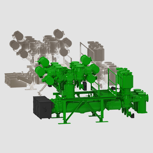
B105 Dual Gas GIS
The B105g SFâ-free GIS is part of GRiDEA, our portfolio of solutions designed to...
View MoreF35g
SF₆-free g³-Gas-Insulated Substations up to 145 kV
GE Vernova's F35g is a g³-gas-insulated substation up to 145 kV, up to 3,150 A and 40 kA using GE Vernova’s revolutionary g³ gas mixture as an insulating and switching alternative to SF₆.
The F35g g³-GIS is designed to deliver the same performances and reliability features as today’s existing SF₆ switchgear, without SF₆'s environmental impacts. Compared to SF₆ switchgear, they feature:
F35g
SF₆-free g³-Gas-Insulated Substations up to 145 kV
GE Vernova's F35g is a g³-gas-insulated substation up to 145 kV, up to 3,150 A and 40 kA using GE Vernova’s revolutionary g³ gas mixture as an insulating and switching alternative to SF₆.
The F35g g³-GIS is designed to deliver the same performances and reliability features as today’s existing SF₆ switchgear, without SF₆'s environmental impacts. Compared to SF₆ switchgear, they feature:
Main Characteristics
Environment friendliness
- SF₆-free using GE Vernova’s g³ gas mixture instead of SF₆
- No pollution transfer in form of raw material increase
- GWP of the gas mass reduced by 99%
- Advanced sealing system
High availability
- Same principles, interfaces, operating mechanisms for both product in g³ and SF₆
- Easy access to drives and accessories
- Pure-spring circuit breaker drives
Low costs of land and civil works
- One of the most compact GIS with bay footprint up to 45% below market average depending on kV rating allows to have low civil work and compact switchgear buildings
- Up to 2 bays 145 kV assembled, wired, tested and shipped
- Isolating device for voltage transformer and surge arrester
Smart Grid ready
- Smart grid features including full-digital monitoring, control and protection
- One of the best experiences and high data reliability
- Digital substation ready with LPITs (Low Power Instrument Transformers)
Specifications
| General ratings | |
| Reference electrotechnical standards | IEC |
| Voltages | Up to 145 kV |
| Insulating and switching medium | g³ gas mixture |
| Withstand voltages | |
| Short-duration power-frequency, phase-to-earth / across isolating distance | 275/315 kV |
| Lightning impulse, phase-to-earth / across isolating distance | 650/750 kVp |
| Frequency | 50 Hz |
| Continuous current | up to 3150 A |
| Short-time withstand current | 40 kA |
| Peak withstand current | 108 kAp |
| Duration of short-circuit | 3s |
| Circuit-breaker ratings | |
| First-pole-to-clear factor | 1.5 |
| Short-circuit breaking current | 40 kA |
| Short-circuit making current | 108 kAp |
| Operating sequence | O-0.3s-CO-3 min-CO |
| Drive type (three-phase or single-phase) | Pure-spring |
| Breaking time | 50ms |
| Closing time | 95ms |
| Mechanical endurance | M2 class |
| Capacitive switching | C2 class |
| Disconnector and low-speed earthing switch ratings | |
| Capacitive current switching | 0.1 A |
| Bus-transfer current switching capability | 2520/20 A / V |
| Mechanical endurance | M2 class |
| Make-proof earthing switch ratings | |
| Making current capability | 108 kAp |
| Switching capability - electromagnetic coupling | 80/2 A / kV |
| Switching capability - electrostatic coupling | 2/6 A / kV |
| Mechanical endurance | M1 class |
Recommended Products & services
F35 72.5 <span class="text-lowercase">k</span>V GIS for Wind Turbines
Welcome to the Future of Wind Power: 72.5 kV Gas-Insulated Substations The offshore wind...
View More
SF₆ and g³ Gas-Insulated Substations
GE Vernova provides GIS solutions from 50 kV to 800 kV, along with smart devices to...
View More
B105 Dual Gas GIS
The B105g SFâ-free GIS is part of GRiDEA, our portfolio of solutions designed to...
View MoreGPM-F Field Ground Protection Module
Complete generator system protection
The field ground protection module, GPM-F works in combination with the Multilin G60 to detect ground faults in the field winding of the generator. Providing application flexibility, the field ground protection module can be configured for either single point injection or double point injection based on application requirements. The solution includes: two stage field ground detection, injected voltage and current supervision, brush lift-off detection, field over and under current elements and field ground fault location.
GPM-F Field Ground Protection Module
Complete generator system protection
The field ground protection module, GPM-F works in combination with the Multilin G60 to detect ground faults in the field winding of the generator. Providing application flexibility, the field ground protection module can be configured for either single point injection or double point injection based on application requirements. The solution includes: two stage field ground detection, injected voltage and current supervision, brush lift-off detection, field over and under current elements and field ground fault location.
Protection
- Two stage field ground resistance based element - 64F
- Wide range fault resistance coverage (1- 500Kohms)
- Injection frequency range 0.1 – 3Hz based on field winding capacitance
- Fault location feature while using single point injection
- Brush-lift off detection
- Injection blocking input for field flashing condition
- Supports redundant G60 configurations
- Field over current and field under current elements using dcmA input of G60
Diagnostics
- Power swing blocking and out-of-step tripping
- Backup distance
- Reverse / low forward power
- Restricted ground fault
- Overexcitation
- Generator unbalance
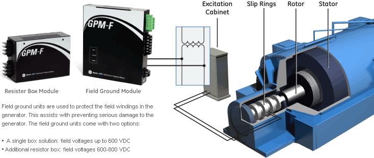
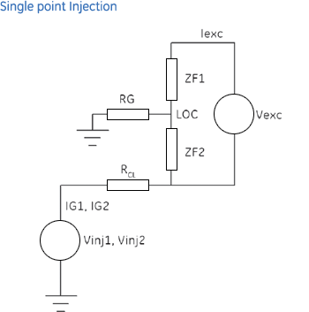
Providing application flexibility and diagnostic information, single point injection provides the ability to quickly identify the fault location in the field winding, thus reducing damaging the generator and reducing down-time. Single point injection has traditionally been the protection method used for generators with brushless excitation.
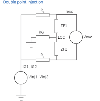
In addition to single point injection, the GPM-F module allows for ground fault detection via double point injection. Double point injection has typically been used on applications where generators are equipped with static excitation. When the GPM-F is connected for double point injection the fault location feature is not available. It is recommended that is fault location is required that the GPM-F be configured for single point injection.


GPM-S
Complete Generator System Protection
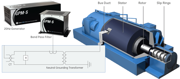
Stator ground module works in combination with GE Vernova’s Multilin G60 and MiCOM Agile P345 to provide a 100% stator ground fault protection that is operational during generator start-up, running and stopped conditions. In the 100% stator ground fault protection based on sub-harmonic injection, a 20Hz voltage is injected to detect ground faults at any point across 100% of the winding thereby protecting the complete stator winding and allowing early detection of stator ground fault conditions.
GPM-S
Complete Generator System Protection
Stator ground module works in combination with GE Vernova’s Multilin G60 and MiCOM Agile P345 to provide a 100% stator ground fault protection that is operational during generator start-up, running and stopped conditions. In the 100% stator ground fault protection based on sub-harmonic injection, a 20Hz voltage is injected to detect ground faults at any point across 100% of the winding thereby protecting the complete stator winding and allowing early detection of stator ground fault conditions.
Protection.
- Two stage stator ground resistance based element – 64S
- Wide range fault resistance coverage (1-20Kohms)
- Over current element for low resistance faults
- CT phase angle error compensation
Diagnostics
- Sub-harmonic voltage supervision
- Sub-harmonic current supervision
- Extensive internal diagnostics in the module with critical-fail relay
- The 100% stator ground fault protection is based on sub-harmonic injection
- 20Hz voltage is injected to detect ground faults at any point across 100% of the winding
- The stator ground module works in combination with the G60 or P345 to provide 100% stator ground fault protection
- Operational during generator start-up, running and stopped conditions
20 Hz Injection Module
Using sub-harmonic injection provides early detection of stator ground fault conditions. This is accomplished by the injection module generating a square wave pulse of 20Hz with a magnitude of +/-26V into the stator winding. The injection module monitors the frequency and magnitude of the signal it generates which allows for the Stator module to determine if a ground fault has occurred in the stator winding. In addition, the stator module is also equipped with a critical-fail relay that can be wired to alarm failure of the module.
Coupling Filter
The coupling filter is used to meet two functions: to smooth the square wave and convert it into a sine wave and to protect the injection module from AC voltage impressed from the secondary of neutral grounding transformer. Coupling filter contains only passive components. It also contains voltage divider circuits to be used on applications with NGT secondary voltage greater than 500V
Multilin 889
Comprehensive Protection and Management
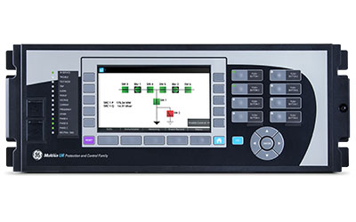
The Multilin 889 relay, a member of the Multilin 8 Series protective relay platform, has been designed for the protection, control, monitoring and management generators and in-zone transformers used in both industrial and utilities applications.
The Multilin 889 provides advanced, high-speed protection, extensively customizable programmable logic, and flexible configuration capabilities, to maximize the operational performance and life of critical generators.
Multilin 889
Comprehensive Protection and Management
The Multilin 889 relay, a member of the Multilin 8 Series protective relay platform, has been designed for the protection, control, monitoring and management generators and in-zone transformers used in both industrial and utilities applications.
The Multilin 889 provides advanced, high-speed protection, extensively customizable programmable logic, and flexible configuration capabilities, to maximize the operational performance and life of critical generators.
Full Color Graphical HMI Front Display
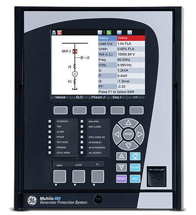
A large, full color Graphic Control Panel (GCP) ensures clear representation of critical status and measurements. The 8 Series offers two options for front panels:
- 10 Programmable Push buttons with 12 programmable LEDs
- 3 Programmable Push buttons and 12 programmable LEDs
Switchgear Control and Configurable SLD
The Multilin 8 Series provides a configurable dynamic SLD up to six (6) pages for comprehensive switchgear control of up to 3 breakers and 9 disconnect switches; including interlocks. Up to 15 digital and metering status elements can be configured per SLD page.
Platform Overview
The Multilin 8 Series platform delivers the highest level of quality, reliability and performance with…
Innovative Technology & Design
- Patented environmental monitoring and diagnostics helps visibility on change in environmental parameters
- Advanced, flexible and embedded communications: IEC® 61850 Ed2, IEC 62439/PRP, Modbus® RTU & TCP/IP, DNP3.0, IEC 60870-5-104, IEC 60870-5-103
- Single setup and configuration across the platform
- Field swappable power supply
- Draw-out design simplifies testing, commissioning and maintenance, thereby increasing process uptime
- Optional Wi-Fi connectivity minimizes system configuration and provides safe relay programming and diagnostic retrieval
- Elimination of electrolytic capacitors
Exceptional Quality & Reliability
- IPC A-610-E Class 3 Manufacturing standards – highest industry standards for electronic manufacturing
- Highest reliability standards for electronics testing
- Environmental Stress Screening and full functional testing
- Rated for IP54 applications
- Standard Harsh Conformal Coating
Uncompromising Service & Support
- Covered under GE Vernova’s 10 year warranty plan
- Fully designed, tested and assembled at GE Vernova facilities

Multilin 889 Overview
The 889 has been designed for the protection, control, and management of generators and associated unit transformers in critical utility and industrial applications.
Applications:
- Comprehensive protection from small to large generators
- Industrial or utility power generation
- Co-generation and renewable generation applications
- Unit Transformer Protection applications
Multilin 889 feeder protection relay functional block diagram
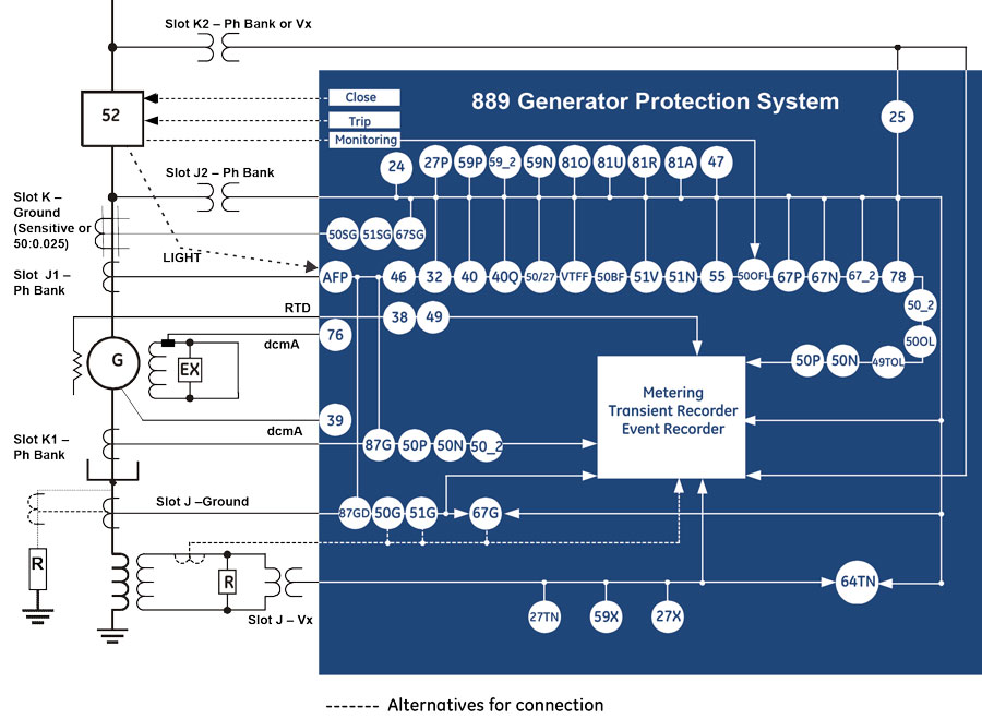
ANSI Device Numbers & Functions
| Device Number | Function |
|---|---|
| 24 | Volts per Hertz |
| 25 | Synchrocheck |
| 27P | Phase Undervoltage |
| 27X | Auxiliary Undervoltage |
| 27TN | Third Harmonic Neutral Undervoltage |
| 32 | Directional Power |
| 38 | Bearing Overtemperature (RTD) |
| 39 | Bearing Vibration (dcmA) |
| 40 | Loss of Excitation |
| 40Q | Reactive Power |
| 46 | Generator Unbalance |
| 47 | Phase Reversal |
| 49 | Thermal (RTD) |
| 49TOL | Thermal Overload |
| 50/27 | Inadvertent Energization |
| 50BF | Breaker Failure |
| 50G | Ground Instantaneous Overcurrent |
| 50SG | Sensitive Ground Instantaneous Overcurrent |
| Device Number | Function |
|---|---|
| 50N | Neutral Instantaneous Overcurrent |
| 50P | Phase Instantaneous Overcurrent |
| 50_2 | Negative Sequence Instantaneous Overcurrent |
| 50OFL | Offline Overcurrent |
| 50OL | Overload |
| 51G | Ground Time Overcurrent |
| 51N | Neutral Time Overcurrent |
| 51SG | Sensitive Ground Time Overcurrent |
| 51V | Voltage Restrained Time Overcurrent |
| 55 | Power Factor |
| 59N | Neutral Overvoltage |
| 59P | Phase Overvoltage |
| 59X | Auxiliary Overvoltage |
| 59_2 | Negative Sequence Overvoltage |
| 64TN | 100% Stator Ground using 3rd Harmonic Voltage Differential |
| 67G | Ground Directional Overcurrent |
| Device Number | Function |
|---|---|
| 67N | Neutral Directional Overcurrent |
| 67P | Phase Directional Overcurrent |
| 67SG | Sensitive Ground Directional Overcurrent |
| 67_2 | Negative Sequence Directional Element |
| 76 | Excitation Current Protection (dcmA) |
| 78 | Out-of-Step Protection |
| 81A | Frequency out-of-band |
| 81O | Overfrequency |
| 81U | Underfrequency |
| 81R | Frequency Rate of Change |
| 87G | Generator Stator Differential |
| 87O | Overall Unit (Gen-Xfrm) Protection |
| 87GD | Restricted Ground Fault |
| AFP | Arc Flash Protection |
| VTFF | VT Fuse Failure |
Generator Stator Differential Protection
The 889 utilizes high-speed dual slope differential protection for detecting and clearing of stator phase faults. Advanced CT saturation detection algorithms maintain immunity to saturation conditions that may be caused due to external disturbances through the use of a directional check that provides additional supervision and ensures the fault is internal to the generator before triggering it to trip.
Overall Generator & Transformer Differential Protection
The 889 can provide overall generator and transformer differential protection (87O). It covers the protection zones from the generator neutral to the GSU (Generator Step-Up) transformer’s High Voltage (HV) winding. This additional protection element provides backup to both Generator Stator Differential (87G) and a dedicated transformer differential in a transformer relay (i.e.: Multilin 845 Transformer Protection System). The 889 with this Generator-Transformer Differential protection supports transformer setup, provides enhanced protection security by including both restrained and unrestrained (instantaneous) differential protection.
100% Stator Ground
100% stator ground fault protection is provided through an overvoltage element and an adaptive voltage differential feature responding to the unbalance of the third harmonic at the machine terminals and at the neutral point. The 889 compares the machine neutral voltage and ground current to determine if ground directional faults are within or outside the generator.
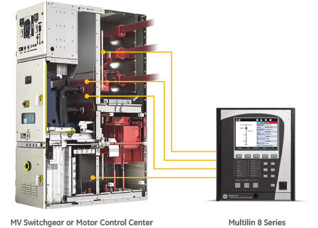
Integrated Arc Flash Protection
The Multilin 8 Series supports an integrated arc flash module providing constant monitoring of an arc flash condition within the switchgear, motor control control centers, or panelboards. With a 2ms protection pass, the 8 Series is able to detect light and overcurrent using 4 arc sensors connected to the 8 Series relay. In situations where an arc flash/fault does occur, the relay is able to quickly identify the fault and issue a trip command to the associated breaker thereby reducing the total incident energy and minimizing resulting equipment damage.
Self-monitoring and diagnostics of the sensors ensures the health of the sensors as well as the full length fiber cables. LEDs on the front panel display of the 889 can be configured to indicate the health of the sensors and its connections to the relay.
 Fast, reliable arc flash protection with light-based arc flash sensors integrated within the Multilin 8 Series of protection & control devices. With arc flash detection in as fast as 2msec, the costs associated with equipment damage and unplanned down
Monitoring & Diagnostics
The Multilin 889 includes high accuracy metering and recording for all AC signals. Voltage, current, and power metering are built into the relay as a standard feature. Current and voltage parameters are available as total RMS magnitude, and as fundamental frequency magnitude and angle.
Data Logging
The Multilin 889 includes high accuracy metering and recording for all AC signals. Voltage, current, and power metering are built into the relay as a standard feature. Current and voltage parameters are available as total RMS magnitude, and as fundamental frequency magnitude and angle.

Log generator operating parameters to allow for analyzing generator loading and performance over weeks and months.
Dedicated Generator System Monitoring & Control
- Running Hours - The 889 can calculate/accumulate generator running hours, which may be of interest for periodic maintenance. if total running hours exceed the use-setting limit, the function would alarm the condition.
- Frequency OOB Accumulation - The Frequency Out-Of-Band (OOB) Accumulation feature provides diagnostic information and alarms based on the accumulated off-nominal (out-of-band) frequency operation time of a turbine over several frequency bands. This alarm can be used to schedule maintenance or other actions as desired
Advanced Generator Monitoring Diagnosis
The 889 can calculate/accumulate generator running hours, which may be of interest for periodic maintenance. if total running hours exceed the use-setting limit, the function would alarm the condition.
- Bearing vibration (Analog Input)
- Excitation current (Analog Input)
- Any generator transducer (dcmA) input monitoring
- Breaker Health
- Data logger, Oscillography, Event Recorder.
The Multilin 889 offers a comprehensive generator health report that provides an easy-to-read snapshot of a generator's health and operating condition. Based on graphical representation and trend values of the generator historical data, the 889 enables operators and asset managers to identify process issues and maintenance requirements before damage occurs and costly repairs are required.
Trip and Close Circuit Monitoring
The 889 relay provides Trip and Close Circuit Monitoring elements
Breaker Arcing Current
This element calculates an estimate of the per-phase wear on the breaker contacts by measuring and integrating the current squared passing through the breaker contacts as an arc. When the threshold is exceeded in any phase, the relay can set an output operand and set an alarm.
Breaker Health
The 889 relay provides breaker health information by monitoring and analyzing the operation count, arcing energy of breaking current, arcing time, tripping time, closing time and spring charging time if applicable
Environmental Monitoring
The 889 implements a patented environmental monitoring system that measures and provides operating condition information. Reliable and secure operation of the 889 relay and other electronic devices in the vicinity may be affected by environmental factors. The 869 relay has been designed to meet or exceed all required industry standards. Some operating conditions may be beyond those standards and reduce total lifespan of the device.

The 8 Series built-in environmental awareness feature (patent “Systems and methods for predicting maintenance of intelligent electronic devices”) collects the histograms of each operating condition from the point the device is put into service. Monitored environmental conditions include temperature, humidity and transient voltage. These parameters are now available as Flexelement to output alarms in case of limits reached due to Temperature, humidity or surges. (Please confirm if this is the part to replace the existing part).
The 889 implements a patented environmental monitoring system that measures and provides operating condition information. Reliable and secure operation of the 889 relay and other electronic devices in the vicinity may be affected by environmental factors. The 869 relay has been designed to meet or exceed all required industry standards. Some operating conditions may be beyond those standards and reduce total lifespan of the device.
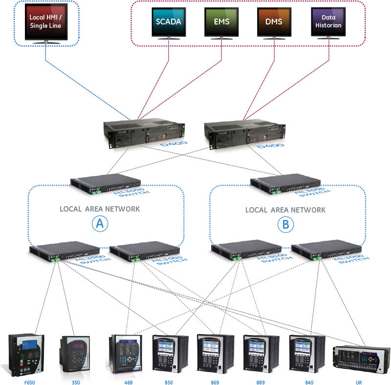
Communications
The 889 provides advanced communications technologies for remote data and engineering access, making it easy and flexible to use and integrate into new and existing infrastructures. Direct support for fiber optic Ethernet provides high-bandwidth communications, allowing for low-latency controls and high-speed file transfers of relay fault and event record information. The 889 also supports two independent IP addresses, providing high flexibility for the most challenging of communication networks.
Providing several Ethernet and serial port options, dual independent Ethernet Ports, and support for a wide range of industry standard protocols, the 889 enables easy, direct integration into DCS and SCADA systems. The 889 supports the following protocols:
- IEC 61850 Ed2, IEC 62439 / PRP
- DNP 3.0, IEC 60870-5-103, IEC 60870-5-104
- Modbus RTU, Modbus TCP/IP
The 889 has two interfaces as USB front port and Wi-Fi for ease of access to the relay. Wi-Fi Connectivity:
- Simplify set-up and configuration
- Simplify diagnostic retrieval
- Eliminate personnel in front of switchgear
- WPA-2 security
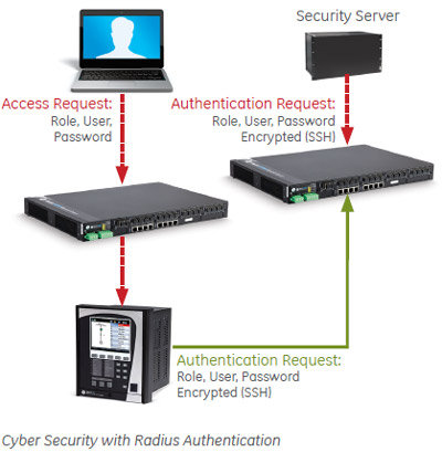
Cyber Security
The 869 cyber security enables the device to deliver full cyber security features that help operators to comply with NERC CIP guidelines and regulations.
AAA Server Support (Radius/LDAP)
Enables integration with centrally managed authentication and accounting of all user activities and uses modern industry best practices and standards that meet and exceed NERC CIP requirements for authentication and password management.
Role Based Access Control (RBAC)
Efficiently administrate users and roles within UR devices. The new and advanced access functions allow users to configure up to five roles for up to eight configurable users with independent passwords. The standard “Remote Authentication Dial In User Service” (Radius) is used for authentication.
Event Recorder (Syslog for SEM)
Capture all cyber security related events within a SOE element (login, logout, invalid password attempts, remote/local access, user in session, settings change, FW update, etc), and then serve and classify data by security level using standard Syslog data format. This will enable integration with established SEM (Security Event Management) systems.
Software & Configuration
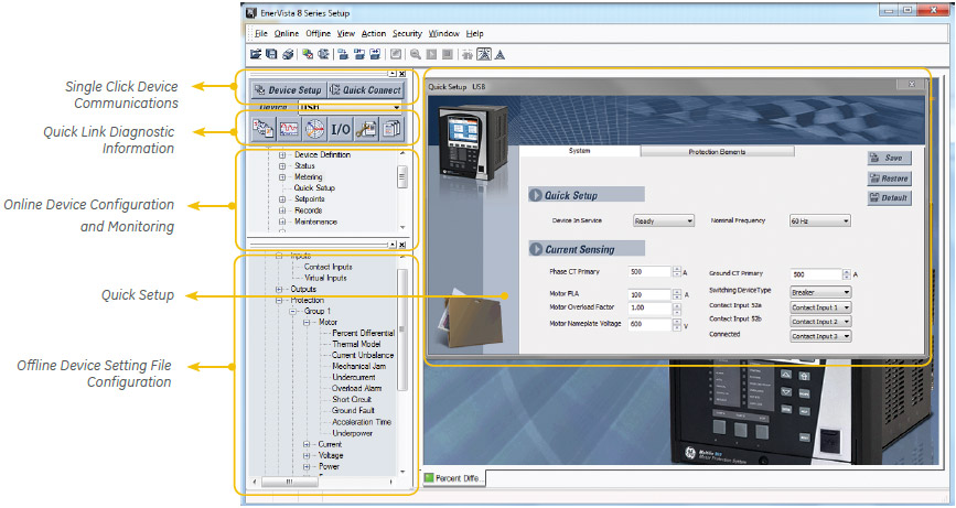
The EnerVista™ suite is an industry-leading set of software programs that simplifies every aspect of using the Multilin 869.
EnerVista provides all the tools to monitor the status of the protected asset, maintain the device and integrate the information measured by the Multilin 8 Series, into SCADA or DCS process control systems. The ability to easily view sequence of events is an integral part of the setup software, as postmortem event analysis is critical to proper system management.
EnerVista Launchpad
The setup tools within Launchpad allow for the configuration of devices in real-time, by communicating via serial, Ethernet or modem connections, or offline by creating device setting files to be sent to devices at a later time.
8 Series Setup Software
8 Series Setup Software is single setup and configuration tool across the platform and can reduce device setup and configuration time.
Simplified Setup & On-Going Maintenance
 Explore the 8 Series Retrofit Kit
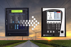
8 Series Retrofit Kit
Retrofit Existing SR 489 Devices to the Multilin 889 in Minutes
Traditionally, retrofitting an existing relay has been a challenging, time consuming task often requiring re-engineering, new drawings, panel modifications, re-wiring and re-testing.
The 8 Series Retrofit Kit provides a quick, 3-step solution to upgrade previously installed SR 489 relays. With the new 8 Series Retrofit Kit users are able to install the 889 Generator Management System without modifying existing cutouts and wiring, and without any drawing changes or re-engineering time.
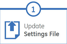
EnerVista 8 Series Setup Software provides automated setting file conversion. Once completed, a graphical report is provided to verify and call out any specific settings that may need attention.
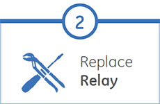
Simply remove the upper, lower and low voltage terminal blocks and then remove the SR chassis from the panel. No need to disconnect any of the field wiring.
Insert the new 8 Series Retrofit chassis into the switchgear and simply plug-in the old terminal blocks - there is no need to make any cut-out modifications or push and pull cables.
Recommended Products & services

Multilin 889
The Multilin 889 relay, a member of the Multilin 8 Series protective relay platform, has...
View MoreMiCOM Agile P34x
Generator Protection Systems
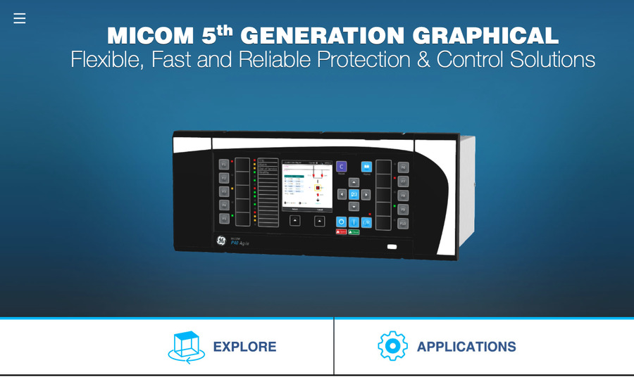
GE Vernova's MiCOM Agile P34x generator protection relays provide flexible and reliable integration of protection, control, monitoring and measurement functions for a wide range of applications. The P34x relay platform is available in six models that cover most installations from small generators to sophisticated systems including generator-transformer applications and large variable speed double fed induction pumped storage machines.
MiCOM Agile P34x
Generator Protection Systems
GE Vernova's MiCOM Agile P34x generator protection relays provide flexible and reliable integration of protection, control, monitoring and measurement functions for a wide range of applications. The P34x relay platform is available in six models that cover most installations from small generators to sophisticated systems including generator-transformer applications and large variable speed double fed induction pumped storage machines.
What's New
The new software features:
- Enhanced power protection with 4 stages of single phase power/VAR (P341-6) and 4 stages of 3 phase power/VAR protection (P341-6)
- New minimum power setting reduced to 0.2%Pn for large generator reverse power applications
- Independent voltage dependent overcurrent (51V) and underimpedance (21) protection
- IEC 61850 Edition 2 support - with support for Ed 2 test modes for online testing.
- IEEE 1588 Precision Time Protocol - efficient time synchronizing direct from the substation LAN.
- Editable Logical Nodes/Devices - to customize the IEC 61850 modelling and maximize interoperability.
- Role based access control (RBAC) for centralized authentication.
- Authorization and account management via RADIUS, and directly on the relay.
- Security Event Management via Syslog.
- Duplicate GOOSE Rejection - Defense against incorrect publishing of out-of-sequence or duplicated GOOSE messages by other devices on the network.
- SNMP version 2c and cybersecure v3 - network management tools can monitor protection IEDs.
- New Ethernet Board - Improved traffic density handling, PRP, HSR and RSTP supported in the same order option for standardization.
Overview
GE Vernova's Agile P34x generator protection solutions provide extensive functionality to meet all generator and generator - transformer applications, including differential protection for fast and selective tripping of phase and earth faults. All generator protection, control, monitoring, recording and communications components are housed within one box, and the solutions are accompanied by a comprehensive library of hardware options, protection and control functions to meet system requirements.
Key benefits:
- Extensive condition based monitoring features for generators and transformers
- Graphical programmable scheme logic eases protection scheme creation and avoids the need for external logic controllers
- Range of different protocols (MODBUS, DNP3, IEC 60870-5-103 and IEC 61850) are available
- IEC 61850 / DNP3.0 redundant Ethernet, supporting self healing ring, RSTP, dual homing, PRP or HSR
- Programmable curves for easy protection customization
Main characteristics:
- Sensitive rotor earth fault protection using low frequency injection method
- Harsh Environment Option to protect against corrosive gases such as H2S or SO2
- Generator and transformer thermal overload, transformer loss of life and through fault monitoring
- Extensive protection for large machines such as pole slipping and 100% stator earth fault protection (3rd harmonic and low frequency injection method)
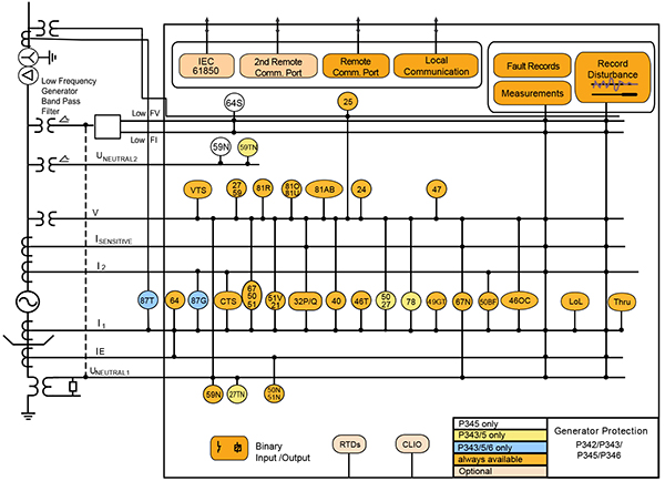
ANSI ® Device Numbers and Functions
| Device Number | Function |
|---|---|
| 87GT | Generator/transformer differential |
| 50DT | Interturn (Split Phase) |
| 50/51/67 | Directional/non directional, instantaneous/time delayed phase overcurrent |
| 50N/51N | Non directionnal, instantaneous/time delayed phase earth fault |
| 67N/67W | Sensitive directional ground fault / wattmetric ground fault |
| 64 | Restricted ground fault |
| 51V | Voltage dependent over current |
| 21 | Under impedance |
| 59N | Neutral voltage displacement/residual overvoltage, interturn -measured,derived |
| 27/59 | Under/Over voltage |
| Device Number | Function |
|---|---|
| 81U/81O/81R | Under/over frequency/rate of change of frequency |
| 81AB | Turbine abnormal frequency |
| 32P/Q | Forward/Reverse, under/over Power/Var |
| 40 | Loss of field |
| 46T | Negative phase sequence thermal |
| 46OC | Negative phase sequence overcurrent |
| 47 | Negative phase sequence overvoltage |
| 49G/T | Stator/Transformer thermal overload |
| 24 | Overfluxing |
| 78 | Pole slipping |
| 27TN/59TN | 100% stator ground fault (3rd harmonic neutral under/over voltage) |
| 64S | 100% Stator ground fault (low frequency injection) with GPM-S |
| Device Number | Function |
|---|---|
| 50/27 | Unintentional energization at standstill |
| 50BF | CB Fail |
| 25 | Check synchronizing |
| 64R | Rotor ground fault (available with CLIO option and P391) |
| RTD | RTD Measurement |
| CTS | CT Supervision |
| VTS | VT Supervision |
| PSL | Programmable Logic |
| TCS | Trip Circuit Supervision |
| Lol/Thru | Loss of life/Thru fault monitor |
Agile P34x Models
P342 Small Generator Management IED.
P343 Medium to Large Sized Generator Management IED
P345 Large Generator Management IED with 100% Stator Earth Fault
P346 Small Generator Management IED with Differential
P348 Variable Speed Double Fed Induction Machine protection IED
P391 Rotor Earth Fault Unit
GPM-S 100% stator earth fault unit (20Hz injection), used with the P345
Manufacturing for P342 has been discontinued. As an alternative, please refer to 889.
Manufacturing for P346 has been discontinued. As an alternative, please refer to P343, 889, G60 or G30.
Manufacturing for P348 has been discontinued. Please contact us to discuss alternatives.
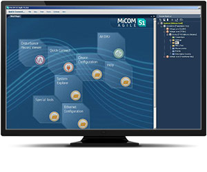
MiCOM S1 Agile
Key benefits:
- Powerful, free of charge, PC toolsuite
- Optimum management of the installed base, structured as per the substation topology
- Intuitive and versatile interface with file management facilities
- Logical structure based on substation, voltage level and bay
- Version control and cross-checking facilities for IED settings
- Real-time measurement visualization – MiCOM S1 Agile extends to all MiCOM Agile IEDs - including P847 PMU and busbar schemes
Engineering Tool Suite
S1 Agile is the truly universal PC tool for MiCOM Agile relay, assemble all tools in a palette for simple entry, with intuitive navigation via fewer mouse-clicks. No-longer are separate tools required for redundant Ethernet configuration, phasor measurement unit commissioning, busbar scheme operational dashboards, programmable curve profiles or automatic disturbance record extraction – applications are embedded. MiCOM S1 Agile supports all existing MiCOM, K-Series and Modulex, including a utility for automatic conversion of setting files from previous generations of numerical relays like K-series and MiCOM P20 to the latest P40 Agile models.
To move to the future, with no loss of functionality, no loss of device support, and full compatibility with your installed base and system architecture – request a copy of S1 Agile with the contact form link below.
Key features in the MiCOM S1 family:
- GE Vernova’s integrated engineering tool that provides users with access to automation IED configuration and record data
- Integrated configuration and monitoring features
- Send and extract setting files
- Event and disturbance record extraction and analysis
MiCOM S1 Agile software request
To receive the MiCOM S1 Agile, please use our Contact form. This will also ensure that you are kept up-to-date with the latest enhancements, including updates and bug fixes.
Refurbishment Solutions
GE Vernova’s latest MiCOM P340 models offer a perfect functional match for LGPG relay from the heritage installed-base brands of GEC Measurements, GEC Alsthom, GE VERNOVA and Areva:
Refurbishment Solutions – “If It’s Blue Think to Renew”
GE Vernova’s latest MiCOM P340 series models P341 to P348 inclusive offer an ideal path to refurbish an older installed base of MiCOM P340 relays. Whether those older products were initially sold as GE VERNOVA or AREVA-branded products, newer models retain pin-pin refurbishment capability. Advantageously, users can benefit from the advancements made in protection, control, communications, hardware that have taken place in the intervening years. The new P40 retains form, fit and function compatibility but delivers the latest platform and software ready for today’s environment, and for future-proofed application for the decades ahead. Pin-Pin Upgrade Methodology:
- Take the order code (CORTEC) of the older relay being removed, typically a blue case relay
- Translate to today’s latest GE Vernova MiCOM model, adding Ethernet options if required
- Order the new P40 relay
- Extract settings and logic, use S1 Agile toolsuite to convert settings
- Detach the terminal blocks from old relay, leaving wiring attached / detach terminal blocks from the new.
- Carefully examine the terminal blocks to see that no physical damage has occurred since installation
- Mount new relay. Old relay blocks fit straight onto the new relay - safer, less wiring to reconnect.
- It is recommended to apply rated current and voltage to the relay CT/VT inputs during secondary injection testing to check the continuity of the CT/VT terminal block connections to the relay.
- Download converted files
- Test, return circuit to service with only minutes of downtime
Contact us for advice and support
Multilin G60
Generator Protection Systems
Built on the industry-leading UR platform, the G60 offers superior protection for medium and large generators, including large steam and combustion turbines, combined cycle generators and multi-circuit hydro units. The G60 may also be used on pumped storage generators without the need to switch the CT secondary circuitry. The G60 provides advanced communication with an integrated, fully managed Ethernet switch reducing network installation costs while supporting industry standard communication protocols.

New and Enhanced Communication Capabilities
- New process bus module supports IEC 61869 sample values, PTP master capabilities and SV switching (FW 7.9x)
- New UR process bus modules supporting IEC61850-9-2LE Merging Units (FW 7.8x) Module Training available here
- Support switchable IEC 61850 Ed. 1 and Ed. 2 and redundant SNTP (FW 7.7x)
- New UR front panel with integrated 7” color, graphical display - providing operators with enhanced situational awareness (FW 7.6x)
- High density I/O module supporting up to 120 inputs or up to 72 contact outputs – eliminating the need for additional discrete devices (FW 7.6x)

Cyber Security - CyberSentry UR (FW v7.xx)
CyberSentryTM enables UR devices to deliver full cyber security features that help customers to comply with cyber security requirements (NERC CIP, IEEE 1686, IEC 62443, etc):
- Secured firmware upgrade: FW file includes hash code that enables authentication prior to being used for upgrading UR Relay (FW 7.9x)

Fully Compatible with IEC 61850-9-2LE or IEC61869 process bus schemes:
- Can connect to up to 8 merging units over -9-2LE or 61869
- Supports PRP, HSR, dual HSR and point-to-point process bus topology
- Provides support for GE Vernova’s IEC 61850 HardFiber Process Bus Solution

Extended Oscillography Records (FW v7.xx)
- Increased number of digital and analog channels (FW 7.90)
- Supports IEEE C37.111-1999/2013, IEC 60255-24 Ed 2.0 COMTRADE 2013 standard (FW v7.40)
- Configurable events allow for records of up to 45s at 64 samples per cycle

New and Enhanced Protection and Control Functionality
- New Inrush detection element (FW 8.0)
- Expanded Bay Controller Capabilities – providing a one box solution (FW 7.6x)
Key Features
- Generator stator differential
- 100% stator ground protection 3rd harmonic
- Field ground protection
- 100% stator ground fault protection using sub-harmonic injection
- Loss of excitation
- Power swing blocking and out-of-step tripping
- Backup distance
- Reverse/low forward power
- Restricted ground fault, thermal overload protection, directional, time, instantaneous, phase, neutral, negative sequence and ground overcurrent protection
- Restricted ground fault
- Overexcitation plus dedicated harmonic/inrush detection
- Overexcitation
- Generator unbalance
- Breaker failure protection
Protection & Control
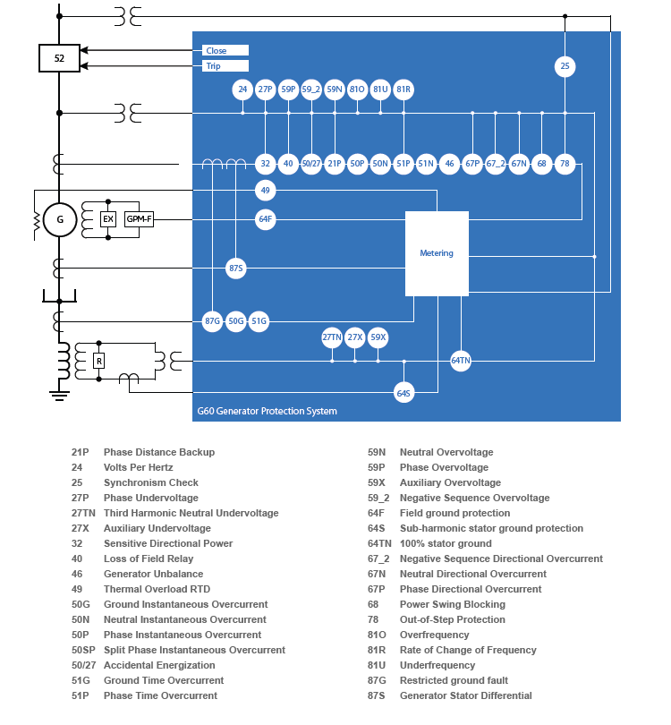
The G60 generator protection system provides comprehensive protection for medium and large generators, including large steam and combustion turbines, combined-cycle generators and multi-circuit hydro units. The G60 includes advanced automation and communication capabilities, extensive I/O options, and powerful fault recording features that can simplify postmortem disturbance analysis and help minimize generator downtime. As part of the UR Family, the G60 provides superior protection and control.
Functional Block Diagram
ANSI® Device Numbers & Functions
| Device Number | Function |
|---|---|
| 21P | Phase Distance Backup |
| 24 | Volts Per Hertz |
| 25 | Synchrocheck |
| 27P | Phase Undervoltage |
| 27TN | Third Harmonic Neutral Undervoltage |
| 27X | Auxiliary Undervoltage |
| 32 | Sensitive Directional Power |
| 40 | Loss of Field Relay |
| 46 | Generator Unbalance |
| 49 | Thermal Overload |
| 50G | Ground Instantaneous Overcurrent |
| 50N | Neutral Instantaneous Overcurrent |
| Device Number | Function |
|---|---|
| 50P | Phase Instantaneous Overcurrent |
| 50SP | Split Phase Instantaneous Overcurrent |
| 50BF | Breaker Failure |
| 50/27 | Accidental Energization |
| 51G | Ground Time Overcurrent |
| 51PV | Phase Time Overcurrent with Voltage Restraint |
| 51N | Neutral Time Overcurrent |
| 59N | Phase Overvoltage |
| 59X | Auxiliary Overvoltage |
| 59_2 | Negative Sequence Overvoltage |
| 59X | Auxiliary Overvoltage |
| 64F | Field Ground Protection |
| Device Number | Function |
|---|---|
| 64S | Sub-Harmonic Stator Ground Protection |
| 64TN | 100% Stator Ground |
| 67_2 | Negative Sequence Directional Overcurrent |
| 67N | Neutral Directional Overcurrent |
| 67P | Phase Directional Overcurrent |
| 68 | Power Swing Blocking |
| 78 | Out-of-Step Protection |
| 81O | Overfrequency |
| 81R | Rate of Change of Frequency |
| 81U | Underfrequency |
| 87G | Restricted Ground Fault |
| 87S | Generator Stator Differential |
Key Features
- Metering - current, voltage, power, energy, frequency
- Oscillography – analog and digital parameters at 64 samples/cycle
- Event Recorder - 1024 time tagged events with 0.5ms scan of digital inputs
- Data Logger - 16 channels with sampling rate up to 1 sample / cycle
- Advanced relay health diagnostics
- P & M class synchrophasors of voltage, current and sequence components – 1 to 120 frames/sec
Monitoring & Diagnostics
 The G60 is the single point for protection, control, metering, and monitoring in one integrated device that can easily be connected directly into DCS or SCADA monitoring and control systems like Viewpoint Monitoring as shown.
Advanced Automation
The G60 incorporates advanced automation features including powerful FlexLogic™ programmable logic, communication, and SCADA capabilities that far surpass what is found in the average generator relay. The G60 integrates seamlessly with other UR relays for complete system protection, including unit and auxiliary transformers, and balance of plant protection.
 FlexLogic allows for the customization of the G60 outputs for most generator protection schemes and applications.
Key Features
Complete IEC 61850 Process Bus solution providing resource optimization and minimizing total P & C life cycle costs
- Three independent 100Mbps Ethernet ports enable purpose specific LAN support that eliminates latency effect of heavy traffic protocols on mission critical communication services
- Embedded IEEE 1588 time-synch protocol support eliminates dedicated IRIG-B wiring requirements for IEDs
- Direct I/O secures high-speed exchange of binary data between URs
- Increase network availability by reducing failover time to zero through IEC62439-3 PRP, HSR or dual HSR support
Advanced Communications
The G60 provides advanced communications technologies for remote data and engineering access, making it easy and flexible to use and integrate into new and existing infrastructures. Direct support for fiber optic Ethernet provides high-bandwidth communications allowing for low-latency controls and high-speed file transfers of relay fault and event record information. The available three independent and redundant Ethernet options provide the means to create fault tolerant communication architectures in an easy, cost-effective manner. The G60 supports the most popular industry standard protocols enabling easy, direct integration into DCS and SCADA systems.
- IEC 61850-9-2LE or IEC 61869 point-to-point or networked or IEC61850-9-2 Hardfiber process bus support
- DNP 3.0 (serial & TCP/IP)
- Ethernet Global Data (EGD)
- IEC 60870-5-103 and IEC 60870-5-104
- Modbus RTU, Modbus TCP/IP
- HTTP, TFTP, SFTP and MMS file transfer
- Redundant SNTP and IEEE 1588 for time synchronization
- PRP as per IEC 62439-3
- Supports Routable GOOSE (R-GOOSE)
Interoperability with Enbedded IEC 61850
Use the G60 with integrated IEC 61850 to lower costs associated with generator protection, control and automation. GE Vernova’s leadership in IEC 61850 comes from thousands of installed devices and follows on years of development experience with UCA 2.0.
The G60’s IEC 61850 Process Bus module is designed to interface with the Multilin HardFiber System, allowing bi-directional IEC 61850 fiber optic communications. The HardFiber System is designed to integrate seamlessly with existing Universal Relay applications, including protection functions, FlexLogic, metering and communications.
The G60 can also connect to GE Vernova MU320 or third-party merging units using standard IEC 61869 or IEC 61850-9-2LE communication protocols.
Cyber Security - CyberSentry™ UR (FW v7.4xx)
CyberSentry enables UR devices to deliver full cyber security features that help customers to comply with NERC CIP and NITIR 7628 cyber security requirements through supporting the following core features:
Secure FW upgrade
UR FW files v7.9 and up now include a hash code that allows for authentication prior to being used for upgrading UR devices.
Password Complexity
Supporting up to 20 alpha- numeric or special characters, UR passwords exceed NERC CIP requirements for password complexity. Individual passwords per role are available.
AAA Server Support (Radius)
Enables integration with centrally managed authentication and accounting of all user activities and uses modern industry best practices and standards that meet and exceed NERC CIP requirements for authentication and password management.
Role Based Access Control (RBAC)
Efficiently administrate users and roles within UR devices. The new and advanced access functions allow users to configure up to five roles for up to eight configurable users with independent passwords. The standard “Remote Authentication Dial In User Service” (Radius) is used for authentication.
Event Recorder (Syslog for SEM)
Capture all cyber security related events within a SOE element (login, logout, invalid password attempts, remote/local access, user in session, settings change, FW update, etc), and then serve and classify data by security level using standard Syslog data format. This enables UR devices integration with established SEM (Security Event Management) systems.
EnerVista™ Software
The EnerVista™ suite is an industry-leading set of software programs that simplifies every aspect of using the G60 relay. The EnerVista™ suite provides all the tools to monitor the status of the protected asset, maintain the relay, and integrate information measured by the G60 into DCS or SCADA monitoring systems. Convenient COMTRADE and Sequence of Events viewers are an integral part of the UR setup software included with every UR relay, to carry out postmortem event analysis and ensure proper protection system operation.

Perception Fleet
Transformer Fleet Risk Management Software System
Continuing its legacy in providing innovative solutions, Perception™ Fleet is GE Vernova's Online Transformer Fleet Management Software System that provides a revolutionary and holistic approach for transformer fleet assessments for utilities and industrial customers around the globe.
Key Benefits

Transformer Fleet Replacement Strategy
- Provides a clear strategic view for asset replacement across the entire fleet
- Tracks the fleet risk index over time to show the improving overall condition of the fleet
- Allows for flexible and scalable transformer fleet risk management

Condition-Based Maintenance Program
- Provides the insight required to shift from costly time-based maintenance to cost effective and focused condition-based maintenance
- Reduces ambiguity and the need to speculate regarding budget requirements
- Reduces OPEX usage on assets to only as required

Automated Data Analysis
- Reduces time required to gather, amalgamate, analyze and interpret transformer diagnostic data
- Provides intelligent algorithms to determine each transformer's condition, and ranks the transformers in the fleet based on their risks
- Reduces reliance on transformer expertise that is rapidly being lost
A Smart Transformer Fleet Management System
Perception Fleet is a smart software solution designed to provide a comprehensive condition evaluation of a transformer fleet. Perception Fleet can analyze and interpret data in order to determine a transformers risk without the need for expert data analysis. Full technical analysis is also instantly available for transformer technical expert use.
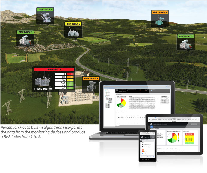
This is accomplished by gathering, amalgamating, analyzing and interpreting the data held on transformers utilizing GE Vernova's online monitoring devices and offline data. The data is analyzed using intelligent algorithms for condition anomalies and characteristics to determine the transformers risk. Each transformer is then assigned a risk index, and they are ranked based on their criticality and risk of failure.
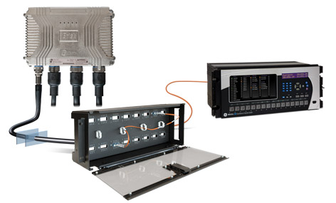
Utilising and evaluating data taken from GE Vernova's online multi gas, single gas and bushing monitoring equipment. Perception Fleet performs an automate risk analysis of transformers focusing on dissolved gas analysis (DGA) of insulation oil, tap changer insulation oil DGA, bushing capacitance, bushing power factor and partial discharge.
The transformer insulation oil properties and quality is also evaluated based on the results received from labs for manually sampled transformer oil. Perception Fleetx's specific offline oil algorithm uses oil analysis techniques outlined by standards, working groups, committees and industry experts to evaluate the condition of the transformer where online monitoring is not available.
Due to the increased and varied level of information provided in lab results Perception Fleet is capable of evaluating a wealth of information beyond pure DGA, as outlined in the brochure.
The automated import facility enables not only the users but their labs to seamlessly update Perception Fleet with the latest data for a manual oil sample analysis. Perception Fleet then performs an automated analysis and evaluation of the newly imported data without the need for any operator interaction.
As well as analysing manually sampled oil data, the offline algorithm can also perform an analysis of oil information from 3rd party online monitors or software applications. The algorithm determines the data available in the imported CSV file received from the 3rd party and performs an evaluation.
Simple Management with Dashboards and Diagnostics
In a world of intelligent and powerful monitoring devices, customers face the problem of data overload making it hard for operators and other users to recognize changes, identify abnormal conditions and react quickly. Perception has used cognitive techniques to build its dashboards for rapid recognition of any change and with extensive use of the traffic light approach that empowers users with at-a-glance recognition of key indicators or important condition changes optimizing reaction time.
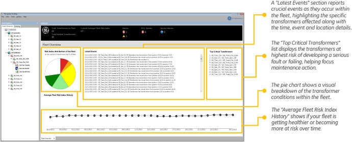
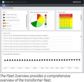
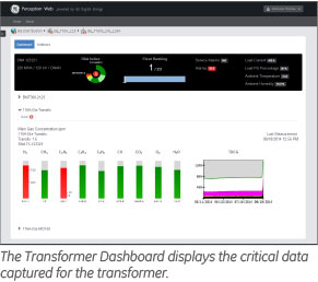
The fleet dashboard provides a comprehensive overview of the transformer fleet, highlighting which transformers are being monitored and risk assessed, how many monitoring devices are experiencing alarms, the overall fleet risk index history and the critical events occurring within the fleet. The device summary dashboard automatically self-configures to show, the most important data from all available online monitoring devices in a simple and concise design.
Standards-Based Management
Perception Fleet incorporates several internationally recognized standards for dissolved gas analysis. These standards are widely considered as the best in class and are attired to by transformer technical experts throughout the world.
The algorithms used in Perception Fleet automatically apply these standards along with best practice techniques against the dissolved gas data received by the GE Vernova online monitoring device. By combining these standards within the algorithms, the software is able to calculate the transformers risk index and score. The algorithm assigned to a transformer can also be weighted in terms of its importance and its sensitive to the parameters adjusted - these adjustments have a direct impact on the algorithm and affects the final risk index and risk score applied to each transformer. Perception Fleet's standards-based algorithms Include:
For a list of all that standards that Perception Fleet is certified to please view the brochure.
Web Interface
Perception Web is a web browser interface for Perception Fleet that provides critical fleet and transformers information via any modern web browser application running on any platform. By using a web browser to interface with Perception Fleet; Perception Web removes the need to install Perception Desktop thereby simplifying and speeding up the Perception Fleet deployment and roll-out process. The information provided via Perception Web is perfect for any user who is interested in viewing the critical fleet and transformer data.
As well as running on a desktop or laptop platform, Perception Web can also be viewed on any Smart Phone or Tablet. The data displays provided by Perception Web are designed to automatically adapt to suit the screen size of the device.
Perception Web can be configured to run as an Intranet or Internet service. The Internet configuration allows users to access and browse the Perception Web data from anywhere on a device with an Internet connection securely. When configured for Intranet access users must be connected to their organisations network infrastructure directly or via a VPN.
Perception Web provides access to the following critical data:
Fleet Overview
Asset Wallboards

Transformer Dashboards
Asset Hierarchy
- Visual representation of the network of areas, substations, transformers and online monitors as preconfigured in Perception Fleet via the Perception Desktop application.
- Click through on an Area or Substation asset to show associated Wallboard.
- Click through on transformer asset to show associated Wallboard or Transformer Dashboard.
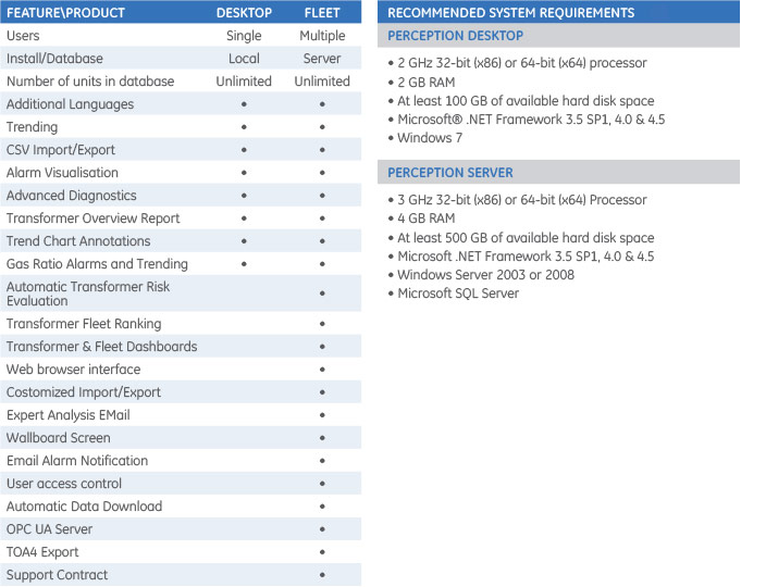
Technical Specifications
Recommended Products & services

Software & Services
Turning data into usable information for operational decisions and fleet management....
View More
Services
GE Vernova recognizes that customers not only want a great product full of features but...
View More
Perception Fleet
Continuing its legacy in providing innovative solutions, Perception⢠Fleet is GE...
View MoreMS 3000
Transformer monitoring system
Benefiting from decades of transformer manufacturing experience and previous transformer monitoring systems (MS 2000), GE Vernova now offers the MS 3000 online condition monitoring and expert system.
The MS 3000 system provides a holistic approach that not only relies on a GE Vernova’s Dissolved Gas Analysis (DGA) monitor but expands the monitoring by connecting to the other existing transformer sensors and adding functionalities and measuring devices as per customer requirements.
MS 3000
Transformer monitoring system
Benefiting from decades of transformer manufacturing experience and previous transformer monitoring systems (MS 2000), GE Vernova now offers the MS 3000 online condition monitoring and expert system.
The MS 3000 system provides a holistic approach that not only relies on a GE Vernova’s Dissolved Gas Analysis (DGA) monitor but expands the monitoring by connecting to the other existing transformer sensors and adding functionalities and measuring devices as per customer requirements.
Recommended Products & services
Kelman BMT 430
An Essential Bushing and Partial Discharge Monitoring Solution
GE Vernova’s latest and advanced Kelman BMT 430 is on-line system that continuously monitors the condition of the bushings, which are constantly under high stress, and developing partial discharge (PD) activity in the transformer. It will immediately alert personnel of evolving fault conditions with the bushings and provide vital health information on the bushings and the transformer.