Multilin 3 Series
Intuitive industrial and utility protective relays for feeders, motors and transformers
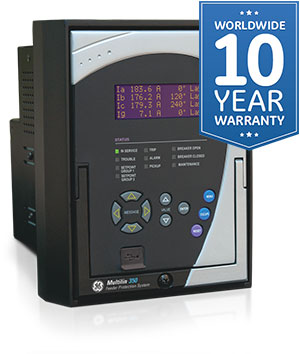
The 3 Series family of protection relays are functional and economical protection solutions for feeders, motors and transformers. By providing protection, control, monitoring and metering, and both local and remote user interfaces in one assembly, the 3 Series family effectively eliminates the need for expensive discrete components. The 3 Series family provide extensive diagnostic information allowing users to troubleshoot and minimize downtime.
Multilin 3 Series
Intuitive industrial and utility protective relays for feeders, motors and transformers
The 3 Series family of protection relays are functional and economical protection solutions for feeders, motors and transformers. By providing protection, control, monitoring and metering, and both local and remote user interfaces in one assembly, the 3 Series family effectively eliminates the need for expensive discrete components. The 3 Series family provide extensive diagnostic information allowing users to troubleshoot and minimize downtime.
Key Features
- Event Recorder: 256 events with 1ms time stamping
- Oscillography with 32 samples per cycle and digital states
- IRIG-B clock synchronization
- Motor health diagnostics
- Security audit trail
Monitoring & Metering
Preventative Maintenance:
The 3 Series allows users to track relay exposure to extreme environmental conditions by monitoring and alarming at high temperatures. This data allows user to proactively schedule regular maintenance work and upgrade activities.
Failure Alarm
The 3 Series detects and alarms on communication port and IRIG-B failures. The 3 Series also enables users to analyze system performance via diagnostics information such as event records, oscillography, etc.
Statistical Data
The 3 Series records statistical data in order to assist in diagnosing common motor faults, as well as assisting in planning preventative maintenance.
Advanced Device Health Diagnostics
The 3 Series performs comprehensive device health diagnostic tests during startup and continuously at runtime to test its own major functions and critical hardware. These diagnostic tests monitor for conditions that could impact and present device status.
Key Features
- 4 X20 character LCD display
- Control panel with up to 12 LED indicator
- Front USB and rear serial, Ethernet and Fiber ports
- Multiple protocols - IEC 61850, ModBus™ RTU, ModBus™ TCP/IP, DNP 3.0, IEC60870-5-104, IEC60870-5-103
Advanced Communications
Easy integration into new or existing infrastructure
With several Ethernet and serial port options, and a variety of communication protocols, the 3 Series provides advanced and flexible communication selections for new and existing applications.
The 3 Series supports various industry standard protocols such as, IEC 61850, Modbus RTU, Modbus TCP/IP, DNP3.0, IEC 60870-5-103 and IEC 60870-5-104 providing simplified and easy integration into new and existing applications.
Drawout Construction
The 3 Series offers a complete drawout feature eliminating the need for rewiring after testing has been concluded. With our advanced draw-out construction, the 3 series can be drawn-out without having to disconnect any communication cables. e.g. fiber, copper, RJ45, etc and helps retain communication status even after a relay has been withdrawn from its case.
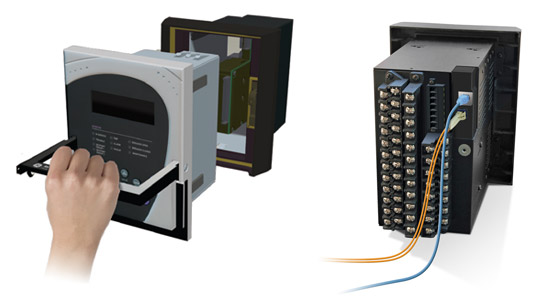 The 3 Series’s advanced draw-out construction allows removal without disconnecting rear communications cables.
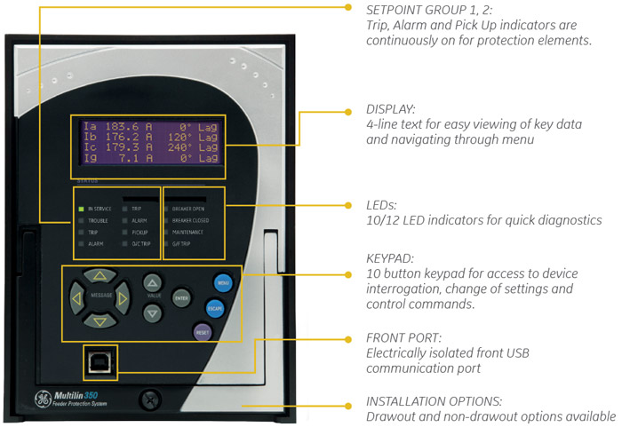
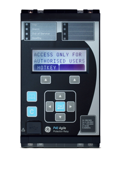
Front Panel
Display
A 4 line liquid crystal display (LCD) allows visibility under varied lighting conditions. When the keypad and display are not being used, system information is displayed by scrolling through a maximum of 30 user-defined default messages. These default messages appear only after a user-defined period of inactivity. The metering summary page is displayed to show original metered values.
EnerVista™ software
Security - enabling NERC CIP compliance
Access Control
Multilin devices and relays are designed with simple but powerful security to enable reliability and compliance for virtually any project or implementation. With support for multi-level permissions and multi-factor supervisory controls, Multilin devices can help you manage the integrity of your system during commissioning, testing, implementation, and beyond. The 3 Series family provides separate authentication for settings and commands to the system. In addition, as discrete authentications for local and remote access, it also provides a supervisory control factor that can lock or unlock a device for configuration changes and other modifications.
Intrusion Detection
Multilin’s family of protection and control products can also help enable your security perimeter and intrusion detection programs. By providing essential alarming and logging of critical events, Multilin devices can help you detect potential breaches within your system and allow you to respond quickly and effectively. Specifically, unsuccessful access attempts are logged, alarmed, and lead to potential attackers being locked out. This ensures the reliability of your system during questionable activity control factor that can lock or unlock a device for configuration changes and other modifications.
Auditing and Reporting
With the Security Audit Trail reporting feature and support for Event logging of key activities such as configuration changes, Multilin devices can help ensure device and protection system integrity, and perform forensic auditing of activities and changes for compliance.
Recommended Products & services
Multilin 3 Series
The 3 Series family of protection relays are functional and economical protection...
View More
Multilin 8 Series
The Multilin⢠8 Series platform of advanced protection and control relays delivers high...
View More
Multilin UR Family
The Universal Relay family of protection and control products are built on a common...
View MoreMultilin 369 - Legacy
Integrated protection and control for medium sized AC motors
Manufacturing for the 369 has been discontinued. As an alternative, please refer to 859.
Multilin 369 - Legacy
Integrated protection and control for medium sized AC motors
Manufacturing for the 369 has been discontinued. As an alternative, please refer to 859.
Key Features
- Enhanced thermal model
- Stall / Jam protection
- Undervoltage, overvoltage
- Underfrequency
- Thermal overload
- Undercurrent/current unbalance
- Variable lockout time
- Overtemperature 12 RTDs (R option)
- Starts/hour, time between starts
- Voltage Phase Reversal (M option)
- Current based phase reversal
- Undervoltage Auto-restart
Protection & Control
The 369 is a digital motor protection system designed to protect and manage medium sized AC motors and their driven equipment. It contains a full range of selectively enabled, self contained protection and control elements as detailed in the Functional Block Diagram and Features table.
Key Features
- Metering - current, voltage, power, energy, frequency, RTD Temperature, Remote RTD
- Fault diagnosis, - Event Record, Oscillography, Motor Starting Data Logger
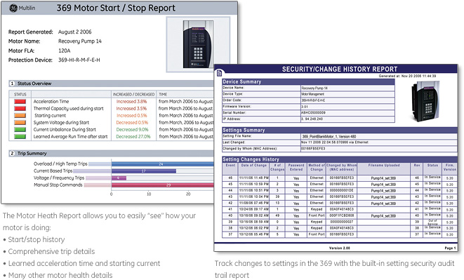
- Motor Health Report
- Statistical information & learned motor data
- Voltage/frequency/power display (M option)
- 4 analog outputs (M option)
Monitoring & Metering
The 369 offers a choice of optional monitoring and metering functions including:
- Actual Values
- Metering (Option M)
- Pre-Trip Alarms
- Event Recorder
- Oscillography
- Statistical Data
- Learned Information
- Motor Start Data Logger
- Testing
 Track changes in motor starting characteristics, identifying potential failures before they become critical
 Troubleshoot faults that occur during motor starts using the Motor Start Data logger.
Key Features
- Front Panel RS232 port for programming and troubleshooting
- Optional embedded Ethernet port
- Optional Profibus DP/DPV1 or DeviceNet via dedicated port
- Multiple Protocols - Modbus RTU, Modbus TCP/IP
A front RS232 port is provided for downloading setpoints and interrogating the relay using the EnerVista™ 369.
Three independent rear RS485 ports offer the customer flexibility and performance for their communication network. The 369 can
communicate at baud rates up to 19,200 bps using the industry standard Modbus® RTU protocol. Fiber optic (option F) Profibus interface (option P), DeviceNet (option D), and Ethernet (option E) ports are also available. The optional direct connect RJ45 Ethernet port can be used to connect the 369 to 10 Mbps Ethernet networks. The communication system of the 369 is designed to allow simultaneous communication via all ports.
Using Ethernet as the physical media to integrate the 369 to Local or Wide Area Networks replaces a multipoint wired
network (e.g., serial Modbus®), and eliminates expensive leased or dial-up connections, reducing operating costs.
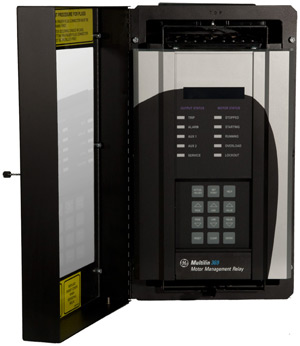
Front Panel
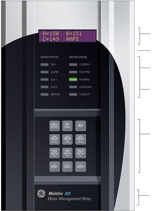
Display
40 Character LCD display for viewing actual values and programming setpoints Rugged, corrosion and flame retardant case
Status Indicators
4 LEDs indicate when an output is activated
Motor Status Indicators
LEDs indicated if motor Stopped, Starting, Running, Overloaded or Locked out due to an active Satart Inhibit element
Keypad
Used to display actual values, causes of alarms, causes of trips, fault diagnosis information, and to program setpoints
Computer Interface
RS232 comm part for connecting to a PC, Use for downloading setpoints, monitoring, data collection & printing reports
EnerVista™ Software
The EnerVista™ Suite is an industry leading set of software programs that will simplify every aspect of using the 369 relay. Tools to monitor the status of the motor, maintain the relay, and integrate information measured by the 369 into HMI or SCADA monitoring systems are available. Also provided are the utilities to analyze the cause of faults and system disturbances using the powerful waveform and Sequence of Event viewers that come with the EnerVista™ 369 Setup Software that is included with each relay. Learn More ![]()
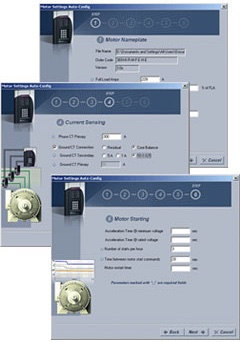
Motor Settings Auto-Configurator
Automatically generate a complete settings file, eliminating the need to manually program hundreds of individual protection settings.
Key Features
- Seamless upgrade for existing Drawout Multilin 269 Motor Management Relays
- Reduce system downtime utilizing the existing Multilin 269 Motor Management Relay drawout chassis
- Reduce maintenance & operational costs - eliminates the need for mounting kits, re-work to existing cutouts and re-wiring of the chassis
- Upgrade with ease using automated setting file conversion tool
- Take advantage of newer, more advanced hardware and feature set
Recommended Products & services

Motor Protection
GE Vernovaâs motor protection systems use advanced thermal modeling to provide...
View MoreMultilin 350
Intuitive and innovative feeder protection system
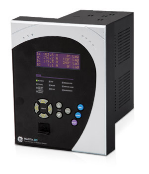
The Multilin™ 350 is a member of the Multilin 3 Series protective relay platform and has been designed for the protection, control and management of feeders or related applications as a primary or backup protection device. This cost-effective protective device is used to perform advanced feeder protection, control and monitoring for low, medium and high voltage applications. The 350 also offers enhanced features such as integrated arc flash protection, metering, monitoring and diagnostics, preventative maintenance, advanced communications and security.
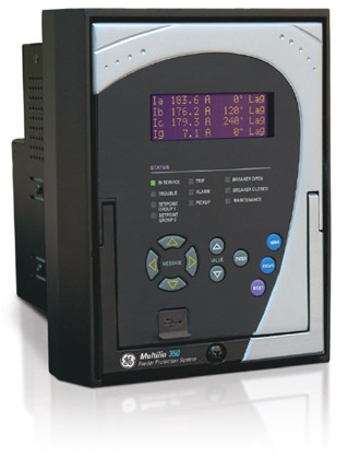
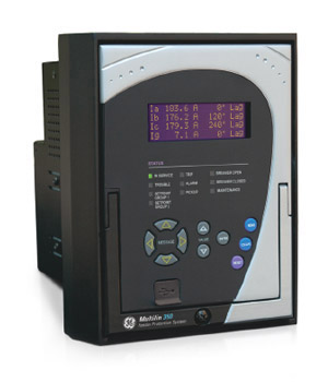
Multilin 350
Intuitive and innovative feeder protection system
The Multilin™ 350 is a member of the Multilin 3 Series protective relay platform and has been designed for the protection, control and management of feeders or related applications as a primary or backup protection device. This cost-effective protective device is used to perform advanced feeder protection, control and monitoring for low, medium and high voltage applications. The 350 also offers enhanced features such as integrated arc flash protection, metering, monitoring and diagnostics, preventative maintenance, advanced communications and security.
Key Features
- Comprehensive current, voltage and frequency protection functions
- Directional Power and Wattmetric Ground Fault
- Wide variety of protection curves
- Synchrocheck, CLP, 2nd Harmonic Blocking, Breaker Failure and Lockout functions
- Cold Load Pick Up
- Breaker failure, overload
- Autoreclose
- Integrated arc flash protection
Protection & Control
The 350 relay is a member of the 3 Series family of Multilin relays. This protective device is used to perform primary or back-up circuit protection on medium or high voltage feeders or transformers and down stream protection for utility and industrial switchgear. The 350 can be used for a wide variety of protection applications in power systems such as HV/MV or MV/LV transformer protection or capacitor bank protection. The basic protection provided by this relay includes multiple phase, ground, and neutral time and instantaneous overcurrent elements for coordination with upstream and downstream devices. Now it is enhanced with integrated arc flash detection functionality using light sensors supervised by over current to reduce incident energy and equipment damage. Additionally, the device provides essential feeder control features such as cold load pick up blocking, 2nd harmonic blocking, breaker failure, synchrocheck and autoreclose.
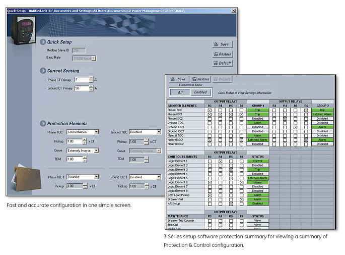
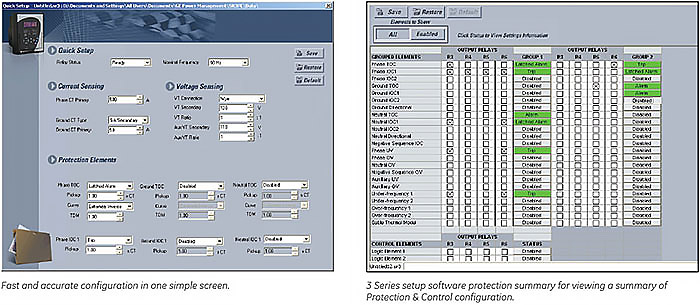
The robust 350 streamlines user work flow processes and simplifies engineering tasks such as configuration, wiring, testing, commissioning and maintenance.
Multilin 350 feeder protection relay functional block diagram
| Device Number | 61850 Logical Node | Description |
|---|---|---|
| 24 | PVPH | Volts per Hertz |
| 25 | RSYN | Synchrocheck |
| 27_1 | psseqPTUV | Positive Sequence Undervoltage |
| 27P | phsPTU | Phase Undervoltage |
| 27X | auxPTUV | Auxiliary Undervoltage |
| 32 | PDOP | Directional Power |
| 32N | ndPDOP | Wattmetric Ground Fault |
| I1/I2 OR 46BC | Broken Conductor | |
| 49 | PTTR | Thermal Overload |
| 50_2 | ngseqPIOC | Negative Sequence Overcurrent |
| 50BF | RBRF | Breaker Failure |
| 50G/SG | gndPIOC/hsePIOC | Ground (or Sensitive Ground) Instantaneous Overcurrent |
| 50N | ndPIOC | Neutral Instantaneous Overcurrent |
| 50P | phsPIOC | Phase Instantaneous Overcurrent |
| 51_2 | ngseqPTOC | Negative Sequence Time Overcurrent |
| 51N | ndPTOC | Neutral Time Overcurrent |
| Device Number | 61850 Logical Node | Description |
|---|---|---|
| 51G/SG | gndPTOC/hsePTOC | Ground (or Sensitive Ground) Time Overcurrent |
| 51P | phsPTOC | Phase Time Overcurrent |
| 59_2 | ngseqPTOV | Negative Sequence Overvoltage |
| 59N | ndPTOV | Neutral Overvoltage |
| 59P | phsPTOV | Phase Overvoltage |
| 59X | auxPTOV | Auxiliary Overvoltage |
| 60CTS | CT Supervision | |
| 67G/SG | gndRDIR | Ground (or Sensitive Ground) Directional Element |
| 67N | ndRDIR | Neutral Directional Element |
| 67P | phsRDIR | Phase Directional Element |
| 79 | RREC | Autoreclose |
| 81O | PTOF | Overfrequency |
| 81U | PTUF | Underfrequency |
| 86 | Lockout | |
| CLP | Cold Load Pickup | |
| VTFF (60VTS) | Voltage Fuse Failure |
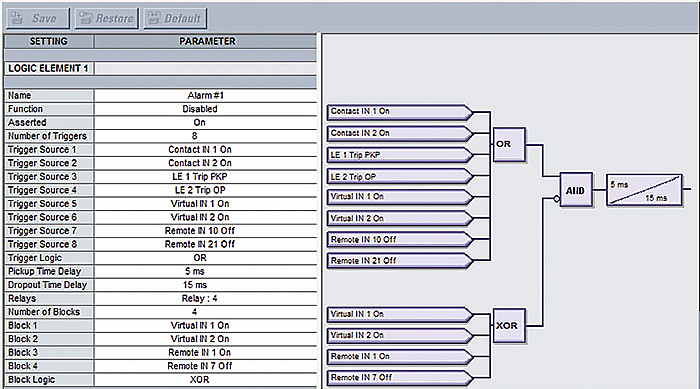 Sixteen logic elements available for applications such as manual control, interlocking and peer to peer tripping.
Key Features
- Comprehensive metering
- Event Recorder: 256 events (1ms time stamping)
- Programmable oscillography up to 32 samples per cycle and digital states and Fault Report
- Relay health diagnostics
- Breaker monitoring and CT/VT supervision
- Security and password control
- SNTP, IRIG-B or IEEE 1588 time synchronization
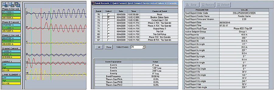
Power System Troubleshooting
Analyze power system disturbances with transient fault recorder and event records
Metering, Monitoring & Diagnostics
IEEE 1588 (Precise Time Protocol) and IRIG-B:
IEEE 1588 synchronizes time between different nodes on an Ethernet network when precise time synchronization is required, and IRIG-B allows time stamping of events to be synchronized among connected devices within 1 millisecond.
Trip/Close Coil Monitoring
The 350 can be used to monitor the integrity of both the breaker trip and closing coils and circuits. The supervision inputs monitor both the auxiliary voltage levels, while the outputs monitor the continuity of the trip and/or closing circuits, by applying a small current through the circuits.
Advanced Device Health Diagnostic:
These diagnostic tests monitor for conditions that could impact and present device status via SCADA communications and front panel display.
Advanced Device Health Diagnostic:
These diagnostic tests monitor for conditions that could impact and present device status via SCADA communications and front panel display.
Key Features
- Front USB and rear serial, Ethernet, fiber and dual port options for seamless redundancy (IEC 62439-3, PRP & HSR)
- Multiple communication protocols supporting industry leading standards
Advanced Communications
The 350 incorporates the latest communication technologies, making it the easiest and the most flexible feeder protection relay for use and integration into new and existing infrastructures. The 350 relay provides the user with one front USB and one rear RS485 communication port. Also available with the 350 is a rear communication port with Ethernet Fiber and Copper. For configurations requiring PRP and HSR redundancy protocols, the 350 provides two rear Fiber ports. Through the use of these ports, continuous monitoring and control from a remote computer, SCADA system or PLC is possible.
The 350 provides optional Parallel Redundancy Protocol (PRP) and High Availability Seamless Ring (HSR) according to the IEC 62439-3 standard that defines two protocols to increase network availability by reducing failover time to zero. Both ports are capable of simultaneously supporting the following protocols: Modbus TCP/ IP, IEC 61850, DNP3 or IEC 60870-5-104, IEEE 1588, SNTP and OPC-UA.
Link Loss Alert (LLA) function detects any issue with one port and switch to the other one in case of failure.
The 350 supports popular industry-leading standard protocols enabling easy, direct integration into electrical SCADA and HMI systems. The protocols supported by the 350 include:
- IEC 61850
- IEC 61850 GOOSE
- DNP 3.0
- Modbus RTU
- Modbus TCP/IP
- IEC 60870-5-103
- IEC 60870-5-104
- PRP & HSR (IEC 62439-3)
- Link Loss Alert (LLA)
- OPC-UA
- IEEE 1588 for time synchronization
Example of redundant HSR and PRP Architecture
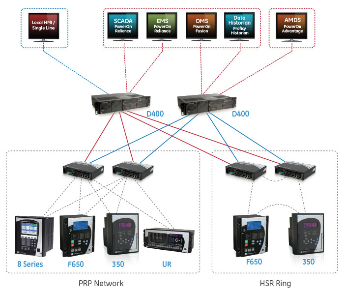 Redundancy protocols can be used for various networking architectures including combined PRP / HSR technologies.
EnerVista Software
The EnerVista suite is an industry leading set of software programs that simplifies every aspect of using the 350 relay. The EnerVista suite provides all the tools to monitor the status of the protected asset, maintain the relay, and integrate the information measured into DCS or SCADA monitoring systems. Convenient COMTRADE and sequence of event viewers are an integral part of the 350 set up software and are included to ensure proper protection and system. Learn More
Access Control
With the Security Audit Trail reporting feature, available in GE Vernova’s ViewPoint Monitoring software, operators are able to obtain Event logging reports of key activities such as configuration changes. These pre-formatted reports can be used to help ensure device and protection system integrity and perform forensic auditing of activities and changes for compliance.
 Trace any setting changes with security audit trail.
Key Features
- 4 line display for easy viewing of key data
- 12/10 LED indicators for quick diagnostics
- Programmable LED indicators for specific targets
- Draw out or non draw out design options
Hardware
Inputs and Outputs
The 350 features the following inputs and outputs for monitoring and control of typical feeder applications:
- 10 contact Inputs with programmable thresholds
- 2 Form A outputs for breaker trip and close with coil monitoring and 5 Form C output relays
Drawout & Non-Drawout Construction
The 350 is offered in both a drawout or a nondrawout construction. In the drawout case design the 350 simplifies installation and improves site safety as the need to open switchgear doors or rewire the device after testing is eliminated.
The 350 protection relay chassis used with a draw out relay is available separately, for use as a partial replacement or in test environments. The draw out relay with no chassis is also available to order as a spare unit.
Application Flexibility & Ease of Wiring
Removable terminals ease wiring and in-system testing or troubleshooting.
Drawout
Non-drawout
User Interface
Retrofit Existing Multilin MII Family Devices
Traditionally, retrofitting or upgrading an existing relay has been a challenging and time consuming task often requiring re-engineering, panel modifications and re-wiring. Similar features and form factor of some models of MII family devices allow users to replace their existing relays with 3 Series relays with enhanced protection and control features and advanced communications.
The SR3 Enervista Setup software allows users to create new setting files based on existing MIFII and MIVII setting files and can be uploaded to a 350 relay with a compatible model number. Retrofit is smooth and simplified with minor wiring or switchgear modifications.
269 and 269Plus - LEGACY
Direct Replacement for Multilin 169, 269, 269Plus and 369 Protection & Control Relays
The Multilin 859 is the only relay that offers a seamless, direct replacement for existing Multilin protection relays. Designed to fit the same mechanical cut and accept the same wiring connectors (applicable to 369 relays), the 859 provides a simplified replacement strategy – eliminating the need for drawing changes, re-wiring, and door modifications. While also significantly reducing any staff training requirements. Additional one-to-one wiring maps are available for other legacy Multilin motor protection relays, and automated setting file conversion and analysis tools ensure reduced configuration time and effort.
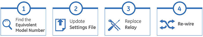
Easy 3-Step Process to Upgrade from 369 to 859, in as fast as 30 minutes
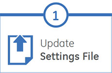
EnerVista 8 Series Setup Software provides automated setting file conversion. Once completed, the relay provides a graphical report to verify and call out any specific settings that might need attention
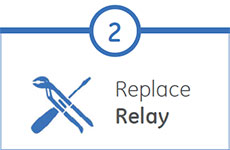
Simply unplug left and right terminal connectors and unscrew the upper and lower terminal wires to remove the 369 relay from the panel. No need to disconnect any of the field wiring*
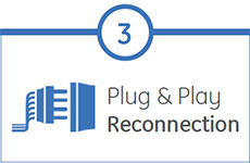
Mount the new 859 relay into the switchgear, plug in the old terminal blocks and reconnect the upper and lower terminal wires – there is no need to make any cut-outs modifications or push and pull old cables
* The panel and all wiring must be deenergized and safety procedures followed
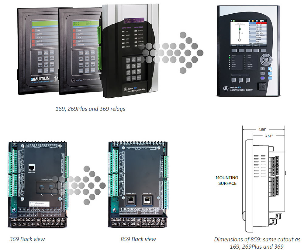
Upgrade your 269 or 269Plus
Drawout to the 369 Drawout
Recommended Products & services
Motor Protection
GE Vernovaâs motor protection systems use advanced thermal modeling to provide...
View More239 Motor Protection Relay - Legacy
Manufacturing for 239 has been discontinued. .
239 Motor Protection Relay - Legacy
Manufacturing for 239 has been discontinued. .
Recommended Products & services
Motor Protection
GE Vernovaâs motor protection systems use advanced thermal modeling to provide...
View MoreMultiSync 100 1588 GPS Clock - Legacy
Modernize time synchronization for power systems
Manufacturing for the MultiSync 100 has been discontinued. As an alternative, please consider the RT430 GNSS clock.
MultiSync 100 1588 GPS Clock - Legacy
Modernize time synchronization for power systems
Manufacturing for the MultiSync 100 has been discontinued. As an alternative, please consider the RT430 GNSS clock.
Cost-Effective, Accurate Time Synchronization
Accurate time synchronization is becoming a critical requirement in today’s power system substations. For example:
- Synchrophasor measurements to support wide area monitoring systems and remedial action schemes require time synchronization accurate down to 1 microsecond
- Merging units, that publish sampled values for use by protective relays, meters, and control devices require time synchronization accuracy of 25 microseconds
- Coordinating fault records and event logs across multiple devices requires time synchronization of 500 microseconds
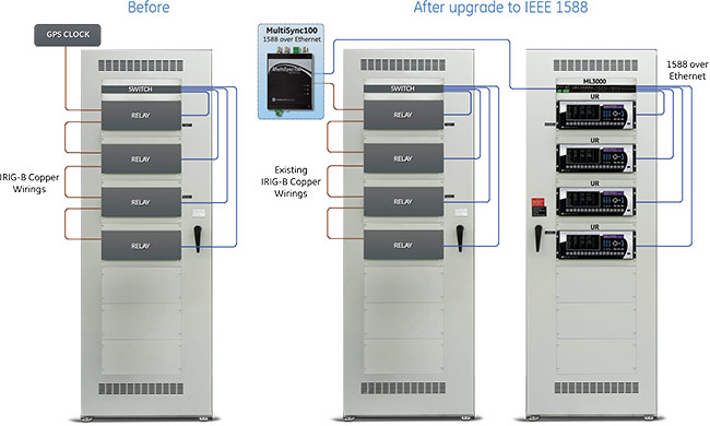
There are two different challenges to the traditional method for time synchronization. The first is that time synchronization has been implemented by connecting end devices to a local satellite clock. This synchronizes all elements in a specific substation together, but this may not be adequate for system wide applications like synchrophasors. The second challenge is that accurate time synchronization has required a dedicated time network.
The most common method employed which provides the accuracy required is IRIB-G. IRIG-B sends out analog pulses, which requires a dedicated analog network built on copper wiring. This network must be installed separately, and is challenged by voltage drop due to distance and the number of connected devices, as well as electrical interference. SNTP/NTP can send time synchronization signals via an Ethernet network, but does not account for switching time delays, and therefore doesn’t meet the accuracy requirements. IEEE 1588 time synchronization provides accuracy to the same level as IRIG-B, over existing Ethernet networks like NTP.
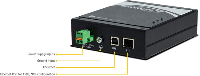
IEEE 1588 Upgrade
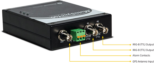
IEEE 1588-2008 is the technical solution designed to provide cost effective time synchronization from devices in a substation up to the whole utility grid. The challenge to implementing 1588 in a substation is interfacing with devices that only support legacy time synchronization methods. The MultiSync 100 1588 GPS Clock is a cost-effective solution to this challenge. Compact size, with DIN rail mounting, provides great flexibility in installation. Network and analog output ports allow interfacing into legacy time synchronization networks while simultaneously providing IEEE 1588 signals.
The MultiSync 100 supports common network time synchronization methods, including IEEE 1588, C37.238 and SNTP/NTP. The MultiSync 100 also supports common analog methods of time synchronization, including IRIG-B, TTL, and user defined pulse methods. The network and analog methods can be supported simultaneously in the MultiSync 100. One compact, affordable MultiSync 100 GPS Clock can provide timing synchronization for 1588 compliant devices and legacy devices in the substation, providing a simple, low cost upgrade path.
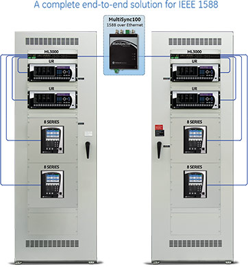
End-to-End Solution for IEEE 1588
The MultiSync 100 is part of a complete end-to-end 1588 time synchronization solution for power system substations and industrial applications. This solution includes:
- MultiSync 100 operating as a GrandMaster clock
- MultiLink ML3001/ML3100 Ethernet switches with 1588 modules
- Universal Relays and 8 Series relays time synchronized to the MultiSync 100
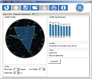 Configuration screen for MultiSync 100.
Ease of Configuration
The MultiSync 100 provides intuitive software to completely configure all aspects of the clock, as well as to display time synchronization data.
Timing and synchronization options include:
- Worldwide daylight savings and local time configuration using rule based or fixed date methods
- Adjustable holdover times for reliability for poor GPS coverage
- Compensation for installation parameters such as GPS signal delay through antenna cable
Programmable digital outputs include:
- IEEE 1588-2008 (v2) , including end-to-end and peer-to-peer implementations
- C37.238-2011, the “Power Profile” for IEEE1588
- NTP / SNTP
Programmable analog outputs include:
- IRIG-B (B00x/B22x) time code with selectable IEEE 1344 and AFNOR S87-500 extensions
- DFC77 time code
- 1000Hz (500ms) pulse
- User defined pulse sequences with repetition
Connection Drawings
Specifications
Kelman TRANSPORT X
Kelman TRANSPORT X
Recommended Products & services
Multiple Gas Transformer DGA
Comprehensive on-line monitoring enabling full remote diagnostics and assured decision...
View More
Kelman MINITRANS
 The MINITRANS is a low-cost on-line discrete multi-gas DGA transformer monitoring...
View More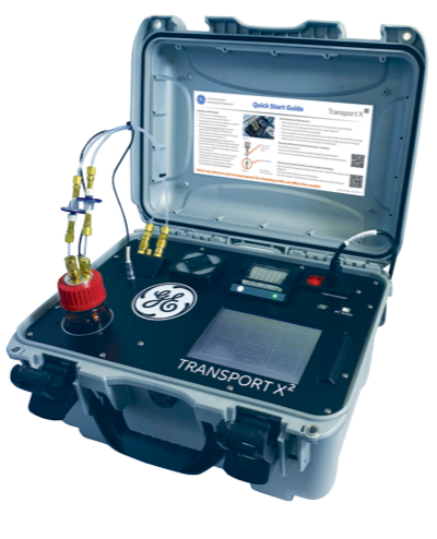
Kelman Transport X²
Dissolved Gas Analysis (DGA) and moisture measurement of insulating fluids are recognized...
View MoreKelman TRANSFIX
The TRANSFIX is an 9-gas on-line transformer DGA monitoring unit. Using specially developed advanced photo-acoustic detection technology, the TRANSFIX measures all significant fault gases (in ppm) as outlined by international standards as well as moisture in oil (%RH & ppm). The measurement of these gases allows the user to detect and diagnose a complete range of transformer faults.
Kelman TRANSFIX
The TRANSFIX is an 9-gas on-line transformer DGA monitoring unit. Using specially developed advanced photo-acoustic detection technology, the TRANSFIX measures all significant fault gases (in ppm) as outlined by international standards as well as moisture in oil (%RH & ppm). The measurement of these gases allows the user to detect and diagnose a complete range of transformer faults.
Recommended Products & services
Multiple Gas Transformer DGA
Comprehensive on-line monitoring enabling full remote diagnostics and assured decision...
View More
Kelman MINITRANS
 The MINITRANS is a low-cost on-line discrete multi-gas DGA transformer monitoring...
View More
Kelman Transport X²
Dissolved Gas Analysis (DGA) and moisture measurement of insulating fluids are recognized...
View MoreTransformer Assessment Service
|
Transformer Assessment Service
|
Recommended Products & services
Transformer Assessment Service
GE Vernova Energy can offer a complete assessment service for large power transformers to...
View MoreKelman TAPTRANS
Recommended Products & services
Multiple Gas Transformer DGA
Comprehensive on-line monitoring enabling full remote diagnostics and assured decision...
View More
Kelman MINITRANS
 The MINITRANS is a low-cost on-line discrete multi-gas DGA transformer monitoring...
View More
Kelman Transport X²
Dissolved Gas Analysis (DGA) and moisture measurement of insulating fluids are recognized...
View More