Multilin Agile Motor Protection
P24N/D Motor Protection Series
GE Vernova’s Multilin Agile Motor Protection, with its compact footprint and advanced feature set, helps to decrease spending to achieve better outcomes.
The Multilin Agile platform offers dedicated motor protection relay with basic to advanced features based on the motor size and application. The relay supports GE Vernova’s proven thermal model for reliable motor protection along with various independent stages of functions to protect against electrical & mechanical faults including Overcurrent /overvoltage/Power & frequency protection.
The relay supports extensive monitoring & recording functions including alarms, events, disturbance records, motor start records etc. along with motor health reports for maintenance team to review, spot trends and take preventive actions.
The relay supports LCD/ large graphical screen option which facilitates effective monitoring & visualization of operational parameters. Advanced cybersecurity option complying to NERC-CIP / IEC62351 standards ensures safety against malicious cyberattacks.
Key Features
- GE Vernova’s proven Thermal model for reliable motor protection
- Motor health report with operating and diagnostic information
- Smaller footprint for easy retrofitting of aging infrastructure
- Intuitive graphical display for effective monitoring, communications & troubleshooting
- Easy testing & commissioning with virtual injection & testing feature
- Draw-out design for simplified testing, commissioning & maintenance
- Cost savings on engineering time & wiring due to traditional hardwired control scheme replacement
Overview
Multilin Agile Feeder P24DB Functional Block Diagram
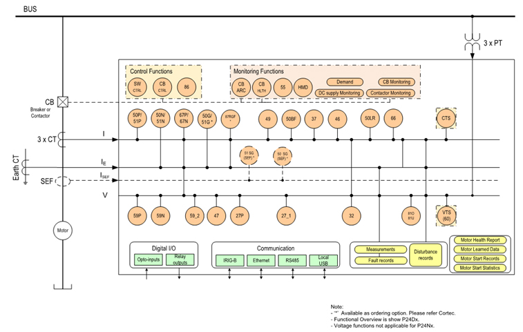
| Device Number | Function |
|---|---|
| 14 | Speed Switch Input |
| 27p | Phase Undervoltage |
| 27_1 | Positive Sequence Undervoltage |
| 32 | Phase directional power |
| 32R | Reverse Power protection |
| 37 | Undercurrent |
| 46 | Current Unbalance |
| 47 | Phase reversal |
| 49 | Thermal Model |
| 50 | Phase Definite Time Overcurrent |
| 51 | Phase Inverse Time Overcurrent |
| 50N/G | Neutral/Ground Definite Time Overcurrent |
| Device Number | Function |
|---|---|
| 51N/G | Neutral/Ground IDMT Overcurrent |
| SEF | Sensitive Earth Fault |
| 50BF | CB Failure |
| 48/50LR | Mechanical Jam (Start/Stalled Protection) |
| 52 | Breaker and Isolator Control |
| 55 | Power Factor |
| 59P | Phase Overvoltage |
| 59_1 | Positive Sequence Overvoltage |
| 59_2 | Negative Sequence Overvoltage |
| 59N | Neutral Voltage Displacement |
| Device Number | Function |
|---|---|
| 66 | Number of starts limitation (start supervision) |
| 67P | Directional Phase Overcurrent |
| 67N/G | Directional Neutral/Ground Overcurrent |
| 68 | Inrush Blocking |
| 81O | Overfrequency |
| 81U | Underfrequency |
| 81V | Undervoltage Blocking |
| 86 | Latching output contacts (Lockout)/Start inhibit |
| 87RGF | Restricted ground fault (REF) |
| ABS | Anti-Backspin (Timer based) |
| Device Number | Function |
|---|---|
| CTS/VTS | CT and VT Supervision |
| THD | Harmonic Measurement/Protection |
| DC Supply Monitoring | |
| CB Condition Monitoring | |
| Overload Alarm | |
| Emergency Restart | |
| Reduced Voltage Starting | |
| Motor Start Records | |
| Motor Health Report |
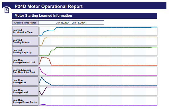
Advanced Motor Health Report
The Multilin Agile health report provides a quick snapshot of the motor operating and diagnostic information in an easy way to allow users to make decisions about health of the motor. Based on the graphical representation and trend values of the motor historical data gathered by the Multilin Agile, users can quickly identify process issues and maintenance requirements before damage occurs and costly repairs are required.
The motor health report quickly provides a motor operation summary with detailed information in seven categories.
- Device Overview
- Status Overview
- Trip Summary
- Motor Operating History
- Motor Starting Learned Data
- Motor Start Records
- Motor Stopping/Tripping
Advanced Communications
Three communication ports are standard: a rear serial port providing remote communications, a front USB port and rear Ethernet for device configuration and management.
Two additional Ethernet ports can be ordered to achieve Ethernet communication redundancy.
Supported Communication Protocols Include:
- Modbus (RS485 serial or Ethernet)
- IEC 60870-5-103
- DNP 3.0 (RS485 serial or Ethernet)
- IEC 61850 Ed. 2 with concurrent serial connection
- Redundant Ethernet protocols PRP, HSR, and failover also available with dual RJ45 or dual fiber media
Flexible Hardware
- Space-saving 4U height with 4” (20TE) and 6“ (30TE) case size options
- Wide choice of opto-isolated binary inputs and output relays
- Binary inputs ESI 48-4 EB2 compliant – avoids spurious pickup from induction on field wiring
- High density I/Os in various combinations depending on case size option
- Ungrouped binary inputs for trip circuit supervision
- Field upgradeable, avoiding costly hardware change
- 6” (30TE) models can accommodate:
- 1 x RS485/IRIG-B interface
- Up to 3 x RJ45/fiber optic ports for single and redundant Ethernet plus additional engineering access
- From 11 to 30 binary inputs, and 9 to 25 relay outputs, depending on the order code
- 4” (20TE) models can accommodate:
- 1 x RS485/IRIG-B interface
- 1 x RS485 additional interface
- Up to 3 x RJ45/fiber optic ports for single and redundant Ethernet plus additional engineering access
- Up to 11 binary inputs and 11 binary outputs or 14 binary inputs and 9 binary outputs, depending on the order code
Simulation & Testing
To aid commissioning, a simulation feature is provided to test the relay’s functionality and response to programmed conditions, without the need for external AC voltage and current inputs. When placed in simulation mode, the relay suspends reading actual AC inputs, generates samples to represent the programmed phasors, and loads these samples into the memory to be processed by the relay. Normal (pre-fault), fault, and post-fault conditions can be simulated to exercise a variety of relay features. Other test operations - such as an LED lamp test for each color, contact input states, and testing of output relays - are also possible.
Application Model Selection
| Model | Hardware Base | Intended Application | Case Size |
|---|---|---|---|
| P24NB | P24N | Motor Protection (current elements only) | 20TE/30TE |
| P24DB | P24D | Motor Protection (current voltage & power elements) | 20TE/30TE |
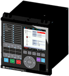
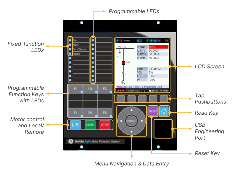
Intuitive User interface
The front HMI hosts a fully-graphical color screen. The front panel supports start, stop, local/remote, and direct function key access, facilitating the control of connected motor and managing up to six controllable devices. These replace traditional hardwired control scheme switches and annunciation, saving on engineering time and wiring costs.
Sixteen tricolor LED lamps are available, freely configurable, in addition to four fixed-function LEDs that provide a cost-effective solution for annunciation.
Multiple language are supported with easy switching between English and an additional language on the local display without uploading new firmware.
A USB front port allows ready access by field personnel’s laptop computers.
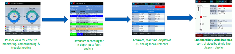
Intuitive Graphical Display
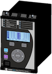
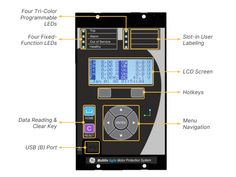
Intuitive User interface – Compact Version
The front HMI hosts a multi-line text display which allows direct device interaction. Smart dependencies within the menu ensure that settings for unused elements are hidden.
Four tricolor LED lamps are available, freely configurable, in addition to four fixed-function LEDs which provide a cost-effective solution for annunciation.
Multiple language are supported with easy switching between English and an additional language on the local display without uploading new firmware.
A USB front port offers ready access by field personnel’s laptop computers.
Recommended Products & services
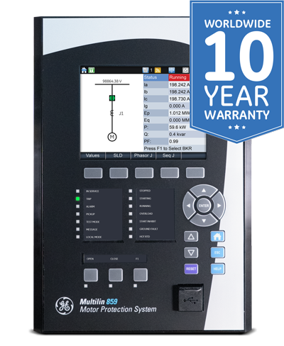
Multilin 859
The Multilin 859 Motor Protection System, a member of the Multilin 8 Series protective...
View More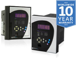
Multilin 339
The Multilin™ 339 is a member of the Multilin 3 Series protective relay platform and...
View More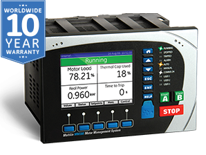
MM300
The MM300 integrates protection, control, automation, metering, diagnostics and multiple...
View More