Multilin 859
Comprehensive and Compact Motor Protection
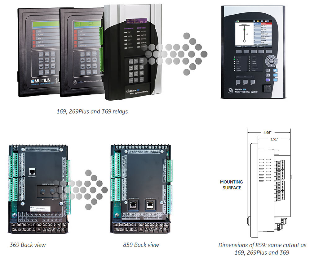
The Multilin 859 Motor Protection System, a member of the Multilin 8 Series protective relay platform, is designed for the protection, control and management of medium and large power rating induction motors. It has also been purpose built as a direct replacement for GE Vernova’s existing range of Multilin motor protection relays including the 169, 269, 269Plus, and 369 devices.
Based on the same field proven hardware and protection and control algorithms of the Multilin 8 Series, the 859 delivers advanced features including high-speed protection, customizable programmable logic, and advanced motor monitoring and diagnostics - all in a fixed mount, slim design.
With extensive communication capabilities the 859 easily integrates into new or existing process control systems, enabling operationally focused motor management and control
To simplify the migration and upgrade from existing Multilin 169, 269/269Plus, and 369 protection relays, the 859 has the same cutout and depth. In the case of replacing a 369 relay, the 859 has the same terminal arrangement, eliminating the need to change field wiring. In the case of other relays, detailed one-to-one wire maps and setting file conversion tools are provided to significantly simplify the upgrade process.
Learn More![]()
Multilin 859
Comprehensive and Compact Motor Protection
The Multilin 859 Motor Protection System, a member of the Multilin 8 Series protective relay platform, is designed for the protection, control and management of medium and large power rating induction motors. It has also been purpose built as a direct replacement for GE Vernova’s existing range of Multilin motor protection relays including the 169, 269, 269Plus, and 369 devices.
Based on the same field proven hardware and protection and control algorithms of the Multilin 8 Series, the 859 delivers advanced features including high-speed protection, customizable programmable logic, and advanced motor monitoring and diagnostics - all in a fixed mount, slim design.
With extensive communication capabilities the 859 easily integrates into new or existing process control systems, enabling operationally focused motor management and control
To simplify the migration and upgrade from existing Multilin 169, 269/269Plus, and 369 protection relays, the 859 has the same cutout and depth. In the case of replacing a 369 relay, the 859 has the same terminal arrangement, eliminating the need to change field wiring. In the case of other relays, detailed one-to-one wire maps and setting file conversion tools are provided to significantly simplify the upgrade process.
Learn More![]()
Multilin 859 Overview
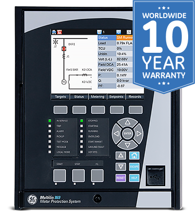
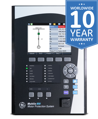
The Multilin 859 Motor Protection System is a protection device for managing, protecting and controlling medium to large horsepower motors.
With a fast protection pass, running every 1/8th of a cycle, the 859 relay provides fast current, voltage, power and frequency protection elements; reducing stress on the motor. The Multilin 859 supports the latest standard communications protocols, including IEC 62439/PRP and IEC 61850 Ed. 2 ; facilitating easy integration into new and existing SCADA/DCS networks.
Key Benefits
- Utilizing GE Vernova's proven Thermal Model for reliable protection of AC induction motors
- With a depth of 3.5", the 859 is ideal for MCCs with shallow depths or space constraints
- Detachable display can be mounted up to 15 feet away from the device, allowing for greater installation flexibility
- Large graphical color LCD display enhanced operability, with user-configurable single line diagrams for local control, system status and metering
- Integrated condition monitoring based on Electrical Signature Analysis, delivering detailed monitoring & analytics for extended motor life
- CyberSentry™ Advanced Security including features such as AAA, Radius, RBAC, and Syslog. helping to enable NERC® CIP compliance
- Safe and reliable motor re-start on ‘down hole’ pump applications. Unique back spin detection feature detects flow reversal on a pump motor, enabling timely and safe motor restarting
- Single setup & configuration software, reducing training & commissioning time
- Customer Support available 24/7, available in multiple languages
Multilin 859 motor protection relay functional block diagram
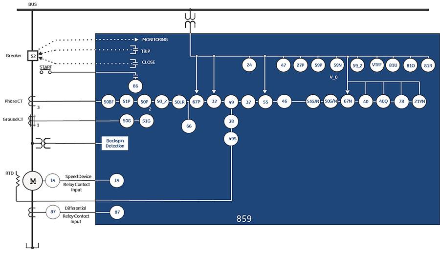
ANSI Device Numbers & Functions
| ANSI DEVICE | DESCRIPTION |
|---|---|
| 12/14 | Over Speed Protection/ Under Speed Protection |
| 21YN | Neutral Admittance |
| 24 | Volts per Hertz |
| 27P | Phase Undervoltage |
| 32 | Directional Power |
| 37 | Undercurrent |
| 37P | Underpower |
| 38 | Bearing RTD Temperature |
| 40 | Loss of Excitation |
| 40Q | Reactive Power |
| 46 | Current Unbalance |
| 47 | Voltage Reversal |
| 48 | Incomplete Sequence |
| 49 | Thermal Model |
| 49S | Stator RTD Temperature |
| 50BF | Breaker Failure |
| 50G | Ground Instantaneous Overcurrent |
| 50SG | Ground Fault |
| 50LR | Mechanical Jam |
| ANSI DEVICE | DESCRIPTION |
|---|---|
| 50N | Neutral Instantaneous Overcurrent |
| 50P | Phase Instantaneous Overcurrent |
| 50_2 | Negative Sequence Instantaneous Overcurrent |
| 51G | Ground Time Overcurrent |
| 51N | Neutral Time Overcurrent |
| 51P | Phase Time Overcurrent |
| 52 | AC Circuit Breaker |
| 55 | Power Factor |
| 59N | Neutral Overvoltage |
| 59P | Phase Overvoltage |
| 59X | Auxiliary Overvoltage |
| 66 | Maximum Starting Rate |
| 67N | Neutral Directional Element |
| 67P | Phase Directional Element |
| 81O | Overfrequency |
| 81U | Underfrequency |
| 81R | Frequency Rate of Change |
| 86 | Start Inhibit |
| VTFF | Voltage Transformer Fuse Failure |
| OTHER |
|---|
| Backspin Detection |
| Undervoltage Restart |
| Autorestart |
| Advanced Electrical Signature Analysis |
| Stator Turn-Turn |
| Broken Rotor Bar |
| Breaker Arcing |
| Breaker Health Report |
| Speed Switch |
| Current Demand |
| kW Demand |
| kvar Demand |
| kVA Demand |
| Starter Failure |
| Motor Health Report |
| Motor Start Report |
| Digital Elements |
| Motor Learned Data |
| Data Logger |
| Harmonics |
| THD |
High-Inertia Load Applications
The voltage-dependent overload curve feature in the Thermal Model protects motors that are used in high-inertia-load applications. Voltage is continually monitored when the motor is started and during acceleration. The thermal-limit curve is then adjusted accordingly. This enables the Multilin 859 to distinguish between a locked-rotor condition, an accelerating condition, and a running condition.
VFD-Driven Motor Applications
The Multilin 859 provides protection for motors fed through VFDs (Variable Frequency Drives). A wide range of the frequency tracking (3-72 Hz) allows the 859 to track the motor frequency and adjust its sampling rate to accurately measure phasors. An advanced algorithm allows switchable current and voltage tracking in case VFD is bypassed.
Thermal protection also considers the extra heating generated by the greater harmonics due to the VFD, to achieve an accurate response to the actual motor heating. RMS currents fed to the various motor-protection elements are further processed through the averaging filter to eliminate oscillations in current signals to ensure security.
Additionally, users can indicate a starting VFD frequency that helps the device track the motor frequency faster. Therefore, the 859 accurately measures the phasor quantities, which, otherwise, could cause delayed or false protection operation.
Cyclic Load Motor Applications
Input currents of a motor driving cyclic load can vary between very small to greater than the maximum allowable current during a load cycle. Variation in current magnitude results in motor heating and cooling depending on the heat and cooling time constants. Thermal overload protection response is adaptive to the cyclic load based on the cooling time constants. In addition, to provide more accurate overload thermal model response to cyclic load, the input currents to the thermal model are averaged over the settable duty-cycle interval. With a reciprocating-load application, the number of cycles to average can be determined from current waveform capture using the Oscillography/Datalogger features in the GE Vernova motor-protection relays
Advanced Motor Monitoring & Diagnostics
The Multilin 859 offers an integrated, cost-effective monitoring and diagnostics features that leverage existing relay data without the need for additional devices, sensors, wiring and training. The 859 utilizes both Electrical Signature (ESA) and Motor Current Signature Analysis (MCSA) to provide the early detection and warning of a wide range of electrical, thermal and/or mechanical abnormalities that may affect a motor’s performance or operational life.
Motor failures and faults can have a significant impact on a process, resulting in loss of revenue and material. Predictive maintenance and situational awareness to the motors operating condition is critical to helping reduce unplanned downtime and energy consumption - maximizing motor life.
Motor monitoring & diagnostic features include stator turn-to-turn fault, broken-rotor-bar detection, roller-bearing faults, foundation looseness, eccentricity, and misalignments.

Electrical Abnormalities
If undetected, insulation failure can evolve into phase or ground faults, causing equipment damage or loss, and significant unplanned downtime. The 859’s advanced motor monitoring and trending capabilities provide identification of critical electrical conditions including:
- Stator inter-turn insulation failure
- Phase-phase insulation failure
- Stator ground failure
- Loss of load/process
- Unbalance current
- Power factor
- Under/Over frequency
Thermal Abnormalities
The 859 continuously and proactively monitors the motor for Thermal Capacity Used (TCU) to provide early warning of thermal stresses including:
- Extreme starting conditions
- Ambient temperature
- Forced cooling stops
- Harmonics
- Single phasing
- Unbalance current
- Increase load
- Locked rotor
Mechanical Abnormalities
Without the need for additional sensors or probes, the 859 utilizes GE Vernova's patented Electrical Signature Analysis (ESA) / Motor Current Signature Analysis (MCSA) to identify mechanical abnormalities in the motor including:
- Broken rotor bar
- Bearing failure
- Mechanical jam
- Static & dynamic eccentricity
- Foundation looseness
- Misalignments
Communications & Cyber Security
The 859 provides advanced communications technologies for remote data and engineering access, making it easy and flexible to use and integrate into new and existing infrastructures. Direct support for fiber optic Ethernet provide s high-bandwidth communications, allowing for low-latency controls and high-speed file transfers of relay fault and event record information. The 859 also supports two independent IP addresses, providing high flexibility for the most challenging of communication networks.
Providing several Ethernet and serial port options, dual independent Ethernet Ports, and support for a wide range of industry standard protocols, the 859 enables easy, direct integration into DCS and SCADA systems. The 859 supports the following protocols:
- IEC 61850 Ed2, IEC 62439 / PRP
- DNP 3.0, IEC 60870-5-103, IEC 60870-5-104
- Modbus RTU, Modbus TCP/IP
The 859 has two interfaces as USB front port and Wi-Fi for ease of access to the relay. Wi-Fi Connectivity:
- Simplify set-up and configuration
- Simplify diagnostic retrieval
- Eliminate personnel in front of switchgear
- WPA-2 security
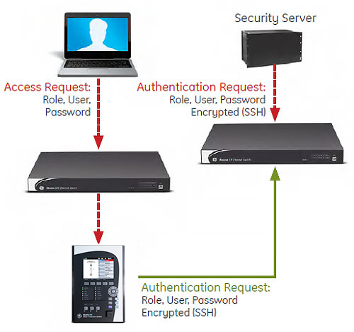
Cyber Security
The 859 cyber security enables the device to deliver full cyber security features that help operators to comply with NERC CIP guidelines and regulations.
AAA Server Support (Radius/LDAP)
Enables integration with centrally managed authentication and accounting of all user activities and uses modern industry best practices and standards that meet and exceed NERC CIP requirements for authentication and password management.
Role Based Access Control (RBAC)
Efficiently administrate users and roles within UR devices. The new and advanced access functions allow users to configure up to five roles for up to eight configurable users with independent passwords. The standard “Remote Authentication Dial In User Service” (Radius) is used for authentication.
Event Recorder (Syslog for SEM)
Capture all cyber security related events within a SOE element (login, logout, invalid password attempts, remote/local access, user in session, settings change, FW update, etc), and then serve and classify data by security level using standard Syslog data format. This will enable integration with established SEM (Security Event Management) systems.
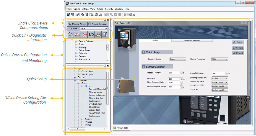
Software & Configuration
The EnerVista™ suite is an industry-leading set of software programs that simplifies every aspect of using the Multilin 859.
EnerVista provides all the tools to monitor the status of the protected asset, maintain the device and integrate the information measured by the Multilin 8 Series, into SCADA or DCS process control systems. The ability to easily view sequence of events is an integral part of the setup software, as postmortem event analysis is critical to proper system management.
EnerVista Launchpad
The setup tools within Launchpad allow for the configuration of devices in real-time, by communicating via serial, Ethernet or modem connections, or offline by creating device setting files to be sent to devices at a later time.
8 Series Setup Software
8 Series Setup Software is single setup and configuration tool across the platform and can reduce device setup and configuration time.
Simplified Setup & On-Going Maintenance
Direct Replacement for Multilin 169, 269, 269Plus and 369 Protection & Control Relays
The Multilin 859 is the only relay that offers a seamless, direct replacement for existing Multilin protection relays. Designed to fit the same mechanical cut and accept the same wiring connectors (applicable to 369 relays), the 859 provides a simplified replacement strategy – eliminating the need for drawing changes, re-wiring, and door modifications. While also significantly reducing any staff training requirements. Additional one-to-one wiring maps are available for other legacy Multilin motor protection relays, and automated setting file conversion and analysis tools ensure reduced configuration time and effort.
Easy 3-Step Process to Upgrade from 369 to 859, in as fast as 30 minutes
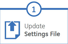
EnerVista 8 Series Setup Software provides automated setting file conversion. Once completed, the relay provides a graphical report to verify and call out any specific settings that might need attention
Simply unplug left and right terminal connectors and unscrew the upper and lower terminal wires to remove the 369 relay from the panel. No need to disconnect any of the field wiring*
Mount the new 859 relay into the switchgear, plug in the old terminal blocks and reconnect the upper and lower terminal wires – there is no need to make any cut-outs modifications or push and pull old cables
* The panel and all wiring must be deenergized and safety procedures followed