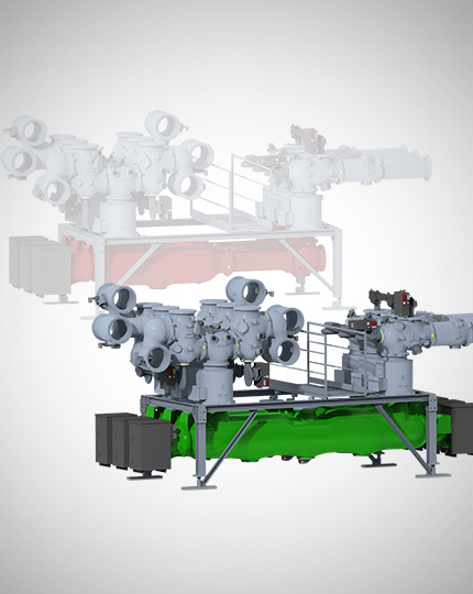
T155g up to 420 kV
SF₆ and g³ Gas-Insulated Substations up to 420 kV
GE Vernova's T155 Dual Gas GIS meets the challenges of networks up to 420 kV for power generation, transmission, and heavy industry applications.
Ready for future SF₆ gas regulations
Anticipating future SF₆ regulations, this Dual-Gas equipment is available with either g³ or SF₆ gas as an insulating and switching medium. Based on having the same foundational design, Transmission System Operators (TSOs) can buy the SF₆ version today and easily switch to GE Vernova’s g³ solution at a later time.
The T155 Dual Gas GIS is very compact and accessible, with a bay footprint equivalent to the previous SF₆ T155 model. Complete bays are fully assembled in the factory (wired, tested, packaged, and shipped), enabling shorter site works.
In addition, the T155 Dual-Gas GIS features an advanced SF₆ sealing system with a sealing length divided by two compared to the previous version, improving tightness.
Full digital monitoring control and protection capabilities enable the T155 Dual Gas to be readily integrated into the smart grid.
Customer Benefits

Characteristics
Sustainability
- 100% SF₆-free version available with T155 Dual Gas GIS (with g³ gas)
- The gas contribution to global warming is reduced by 99% using GE Vernova’s g³ gas instead of SF₆
- First-in-class gas sealing system
- Improved tightness due to sealing length divided by two, compared to the previous version
High availability
- Current transformers located outside SF₆/g³ gas compartment
- Pure-spring circuit breaker drives
- State-of-the-art maintenance isolating device: major repair and HV tests with no more than one bay down
- Outstanding accessibility to drives and accessories
Low costs of land and civil works
- Very compact GIS: bay footprint remains the same as latest SF₆ GIS
Short site works
- Complete bays are fully assembled in the factory (wired, tested, packaged, and shipped)
Smart grid features
- Full-digital monitoring, control and protection
Specifications
| g³ | Combined g³ bay-SF₆ CB | SF₆ | |
GIS Type | T155g 420 kV | T155 420 kV | T155 420 kV |
| Reference electrotechnical standards | IEC | IEC/IEEE | IEC/IEEE |
| Rated voltage | 362-420 kV | 362-420 kV | 362-420 kV |
| Withstand voltages | |||
| Short-duration power-frequency, phase-to-earth/across open switching device | 650/815 kV | 650/815 kV | 650/815 kV |
| Switching impulse, phase-to-earth / across isolating distance | 1050/900(+345) kVp | 1050/900(+345) kVp | 1050/900(+345) kVp |
| Lightning impulse, phase-to-earth / across open switching device | 1425/1425(+240) kVp | 1425/1425(+240) kVp | 1425/1425(+240) kVp |
| Frequency | 50 Hz | 50/60 Hz | 50/60 Hz |
| Continuous current | up to 5000 A | up to 5000 A | up to 5000 A |
| Short-time withstand current | 63 kA | 63 kA | 63 kA |
| Peak withstand current | 170 kAp | 170 kAp | 170 kAp |
| Duration of short-circuit | 3s | 3s | 3s |
| Installation | indoor/outdoor | indoor/outdoor | indoor/outdoor |
Circuit Breaker Ratings | |||
| Short-circuit breaking current | 63 kA | 63 kA | 63 kA |
| Short-circuit making current | 170 kAp | 170 kAp | 170 kAp |
| Operating sequence | O-0.3s-CO-3 min-CO/CO-15s-CO | O-0.3s-CO-3 min-CO/CO-15s-CO | O-0.3s-CO-3 min-CO/CO-15s-CO |
| Drive type | Pure-spring | Pure-spring | Pure-spring |
| Mechanical endurance | M2 class | M2 class | M2 class |
| Capacitive switching | C2 class | C2 class | C2 class |
Disconnector and Low-speed Earthing Switch Ratings | |||
| Capacitive current switching | 0.5 A | 0.5 A | 0.5 A |
| Bus-transfer current switching capability | 3000 A / 20 V | 3000 A / 20 V | 3000 A / 20 V |
| Mechanical endurance | M2 class | M2 class | M2 class |
Make-proof Earthing Switch Ratings | |||
| Making current capability | 170 kAp | 170 kAp | 170 kAp |
| Switching capability-electromagnetic coupling | 160 A / 10 kV | ||
| Switching capability-electrostatic coupling | 18 A / 20 kV | 18 A / 20 kV | 18 A / 20 kV |
| Mechanical endurance | M1 class | M1 class | M1 class |

