High accuracy power quality, power metering and sub-metering solutions

Category image
Metering.jpg
Has legacy products
On

The Multilin™ EPM 7000P is a versatile power quality meter offering that can be used for a wide range of high accuracy revenue and power quality applications for both Utility and Industrial customers.

EPM 7000P

Versatile Power Quality Metering with Logging and Flexible Communications

The Multilin™ EPM 7000P is a versatile power quality meter offering that can be used for a wide range of high accuracy revenue and power quality applications for both Utility and Industrial customers.

Key Features

  • High resolution waveform recording (up to 512 samples/cycle) and high accuracy ANSI C12.20 Class 0.1% accuracy energy metering
  • Easy system integration with support for Modbus (RTU, TCP/IP), DNP 3.0, IEC 61850 Protocols
  • Field upgradeable functionality for future requirements with communications and I/O cards as well as software option functionality upgrades and logging memory (up to 128MB) to log years of captured data
  • Flexible installation mounting with standard ANSI cutout as well as available optional meter enclosures for retrofit applications and no display transducer version (EPM 7000T) for DIN rail mounting

Applications

  • New or retrofit (available enclosures) revenue energy billing or reconciliation (demand, time of use) for utility or industrial applications
  • Power quality studies/alarming/event capture for utility or industrial event investigation/reconciliation, ensuring uptime and predictive maintenance for critical power quality sensitive assets (Utility substation, Data Centers, Manufacturing, Hospitals)
  • Energy metering or power quality monitoring for harsh environments with standard conformal coating

Enhanced Revenue and Power Quality Metering

The EPM 7000P has been designed with features to satisfy both revenue and power quality metering for utility substation and industrial applications.

Accurate Revenue Energy Metering

The EPM 7000P provides several features to support accurate Revenue Energy metering including: an Energy Test Pulse; ANSI C12.20 0.1% and IEC 62053-22 CL 0.2S Accuracy Class certification; Time of Use; CT/PT Compensation.

This allows the EPM 7000P the flexibility and capability to be installed either as a utility or industrial device to ensure accurate readings and assist with reconciliation of energy consumption.

Multifunction Metering & Power Quality Monitoring

The EPM 7000P can provide a total picture usage and power quality as different points within a power distribution network on critical infrastructure such as data centers, allowing users to make power related decisions quickly and effectively.

Multifunction Metering

Configure up to 6 Historical Logs Configure up to 6 Historical Logs Limit log
View System Events View System Events
Limit log viewer" Limit log viewer

Extensive Logging Capability

The EPM 7000P provides up to 128MB of memory for logging.

Through upgradeable Software Options, the memory can be upgraded as requirements change from a multifunction meter with no logging to a logging capability up to 128MB.

The logging capability of the EPM 7000P provides:

  • Detailed information for analysis during Power Quality and/or Load studies
  • Logged data for Historical Logs; Meter System Events; I/O Changes; and Limits/Alarms

Historical Logs

  • Configure logging values with up to 6 assignable historical logs
  • Independently programmed trending profiles
  • Up to 64 parameters per log

System Events Log

To protect critical information captured by the EPM 7000P, the meter records and logs the following System Events with a time stamp to log and track:

  • System startup
  • Programmable settings changes
  • Password requests/sealing switch changes
  • Demand resets
  • Energy resets
  • Log resets
  • Critical data repairs

Input/Output (I/O) Change Log

  • Provides a time stamped log of meter I/O relay outputs; input status changes
  • Ability to capture up to 2048 events

Limit/Alarm Log

  • Provides magnitude and duration of an event
  • Includes time stamps and alarm value
  • Ability to capture up to 2048 events
  • Capability to send Alarm Email with E1 Ethernet card option

Limit Alarms and Control Capability

  • Ability to set up to 16 Limit Alarms on measured parameters
  • Monitor Voltage/Current unbalance
  • Set Alarms based on % of full scale settings

I/O cards
Extensive Communications and I/O Cards

The EPM 7000P provides two universal option slots for communications and/or I/O. The unit can be easily configured to accept new I/O cards even after installation by auto-detecting installed I/O option cards. Up to 2 cards of can be used for communications and or I/O per meter providing a range of integration possibilities.  

Along with I/O expandability the EPM 7000P can integrate with many different systems, using multiple standardized protocols such as Modbus RTU/ASCII/TCP, Level 2 DNP3 and IEC 61850.  Expandable communications cards allows customization for system requirements at time of purchase as well as in the future if requirements change.

Flexible, Expandable Communications and I/O Cards

E1: 100BaseT Ethernet Card (Modbus,DNP3)

  • 12 simultaneous Modbus TCP/IP connections
  • 5 simultaneous Level 2 DNP3 over TCP/IP connections
  • Network Time Protocol (NTP) support for high accuracy network time sync
  • Embedded web server
  • Available support for dual Ethernet Ports

E2: 100BaseT Ethernet with IEC 61850 Protocol

  • Simultaneous Modbus TCP/IP and IEC 61850
  • IEC 61850 Support including:
    • Configurable .CID file
    • 5 Simultaneous MMS Clients
    • Multiple Logical Nodes

C1: Four Channel Bi-directional 0-1mA Outputs

  • Assignable to any parameter
  • 0.1% of Full Scale
  • Max Load Impedance 0 to 10KΩ

C2: Four Channel Bi-directional 4-20mA Outputs

  • Assignable to any parameter
  • 0.1% of full scale
  • 850Ω, at 24VDC
  • Loop powered using up to 24VDC

RS: Two Output Relays/ Two Status Inputs

  • 250VAC/30VDC – 5A Relays, Form C
  • Trigger on user set alarms
  • Set delays and reset delays

PS: Four Pulse Outputs / Four Status Inputs

  • Programmable to any energy parameter or pulse value
  • Form A: Normally Open Contacts
  • Can function for manual relay control and limit based control

F1: Fiber Optic Interface with ST Termination

  • Daisy Chain switchable built-in logic mimics RS485 half duplex bus to support daisy chain for lower installation cost/ effort
  • ST terminated
  • Modbus and Level 2 DNP3 Protocols available

F2: Fiber Optic interface with Versatile Link Termination

  • Daisy Chain switchable built-in logic mimics RS485 half duplex bus to support daisy chain for lower installation cost/ effort
  • Versatile terminated
  • Modbus and Level 2 DNP3 Protocols available

S1: Serial RS232/RS485 Communications

  • Programmable RS485 or RS232 Port
  • Adds up to 2 ports per meter in addition to the standard Serial RS485 port
  • Supports one session at a time of DNP3 serial communication per meter

Comprehensive, Upgradeable Features

Along with basic standard features (Software Option A) the EPM 7000P provides field upgradeable, post installation Software Options. An unlock key for the higher Software Option can be entered in the GE Vernova Communicator Setup software providing more functionality with the same installed unit in the future. The following table illustrates the available features and upgrades.

GE VERNOVA EPM 7000P/PT FEATURESSOFTWARE OPTION ASOFTWARE OPTION BSOFTWARE OPTION CSOFTWARE OPTION D
BASIC MEASUREMENTS
Multifunction Measurement (Voltage, Current)

Time of Use

CT/PT Compensation

Transformer/Line Compensation

POWER QUALITY MEASUREMENTS
THD and Harmonics

Waveform Recording Sampling Rate  

128 Samples/Cycle

512 Samples/Cycle

STORAGE
Memory for logging 

2 MB

10MB

128MB

System Events


Waveform Log


Limit Log

Input Status Change

COMMUNICATION
Modbus

DNP 3.0 Level 2

IEC 61850 (E2 Option)


Waveform Recording Options


Software OptionSamples per CyclePre Event CyclesPost Event CyclesMax Waveform per Event
C163296256
321648128
6482464
12841232
D2562616
512138

Technical Specifications

VOLTAGE INPUT RANGE
  • (20-576) Volts Line To Neutral, (0-721) Volts Line to Line
  • Universal Voltage Input
  • Input Withstand Capability – Meets
  • IEEE C37.90.1 (Surge Withstand Capability)
  • Programmable Voltage Range to Any PT Ratio
  • Supports: 3 Element WYE, 2.5 Element WYE, 2 Element Delta, 4 Wire Delta Systems
  • Input Wire Gauge: AWG#12-26/ (0.129 - 3.31)mm2
ISOLATION
Voltage Inputs galvanically isolated to 2500V AC
CURRENT INPUT RANGE
  • Class 10: (0.005 to 11) A, 5 A Nominal, 18 A max
  • Class 2: (0.001 to 2) A, 1 A Nominal Secondary, 2 A
  • Max Programmable Current to Any CT Ratio
  • Pickup Current: 0.1% of Nominal: Class 10: 5 mA, Class 2: 1 mA
  • Pass Through Wire Diameter: 0.177”/4.6 mm
CURRENT INPUT WITHSTAND CAPABILITY (AT 23 °C)
  • Fault Current Withstand (at 23°C): 100 A for 10 Seconds, 300 A for 3 Seconds, 500 A for 1 Second
  • Continuous Current Withstand: 20 A for Screw Terminated or Pass Through Connections
BURDEN
  • Voltage Inputs: Input Impedance 8Ω; Burden 0.018 W at 120 Volts
  • Current Inputs: 0.005 VA per Phase Max at 11 A
FREQUENCY RANGE
45 to 65 Hz
MEASUREMENT METHOD
  • True RMS
  • Sampling at over 400 Samples/Cycle on all Channels of Measured Readings Simultaneously
  • Harmonics Resolution to 40th Order
  • Waveform up to 512 Samples/Cycle
ACCURACY RATINGS
  • 0.2% Energy Accuracy
  • Note: For 2.5 element programmed units, degrade accuracy by an additional 0.5% of reading
  • Note: For 1A (Class 2) Nominal, degrade accuracy to 0.5% of reading for watts and energy; all other values 2 times rated accuracy
  • Full accuracy specifications available in User Manual
UPDATE RATE
  • Watts, VAR and VA- Every 6 Cycles
  • All Other Parameters – Every 60 Cycles
UPDATE RATE
  • Watts, VAR and VA- Every 6 Cycles
  • All Other Parameters – Every 60 Cycles
CONTROL POWER REQUIREMENTS
  • Option HI: Universal,(90 to 265) Volts AC or (100 to 370) Volts DC
     
  • Option LD: (18-60) Volts DC (24 to 48 V DC Systems)
  • Burden: 10 VA Max
COMMUNICATION

Standard Communications

  • 2 Com Ports (Back and Faceplate)
  • RS485 Port through Backplate
  • USB through Faceplate (uses USB Mini-B connector)
  • Com Port Baud Rate: (1200 - 57600) bps
  • Com Port Address: 1-247
  • 8 Bit, Parity Setting: Odd, Even, None
  • Modbus (RTU, TCP/IP), DNP 3.0 Level 2, IEC 61850 Protocols
  • IEC 61850 available with I/O Slot 1/2 - E2 option
KYZ PULSE
  • Type Form C Contact
  • On Resistance: 35 Ω Max
  • Peak Voltage: 350 V DC
  • Continuous Load Current: 120 mA
  • Peak Load Current: 350 mA (10 ms)
  • Off State Leakage Current @350 V DC: 1uA
ENVIRONMENTAL
  • Operating temp: (-25 to +70) °C
  • Storage temp: (-40 to +70) °C
  • Humidity: Up to 95% RH non-condensing
  • Faceplate Rating: NEMA 12
  • Mounting Gasket Included
  • Standard Conformal Coating
  • Protection: IP30 – Meter Front/Back, Optional DIN Rail
  • Mounting, Optional Plug-in I/O Modules
SHIPPING
  • EPM 7000P Meter Mounts in 92mm DIN or ANSI C39.1, 4"Round Cutout
  • Basic Unit: H4.85" x W4.85" x L4.25"
  • Total shipping weight: approx. 2 lbs (0.91 kg)
  • Shipping container dimensions: 6”x 6”x 6” (15.2cm x 15.2cm x 15.2cm)
COMPLIANCE
  • ANSI C12.20 0.1% Accuracy Class
  • ANSI (IEEE) C37.90.1 Surge Withstand
  • ANSI C62.41 (Burst)
  • IEC 61000-4-2 – Electromagnetic compatibility (EMC); Testing and measurement techniques; Electrostatic discharge immunity test
  • IEC 61000-4-3 – Electromagnetic compatibility (EMC); Radiated, radio frequency, electromagnetic field immunity test
  • IEC 61000-4-4 – Electrical fast transient/burst immunity test
  • IEC 61000-4-5 – Surge immunity test
  • IEC 61000-4-6 – Immunity to conducted disturbances, induced by radio-frequency fields
  • IEC 61000-4-7 – General guide on harmonics and inter-harmonic measurements and instrumentation
  • IEC 61000-4-8 – Magnetic field immunity
  • IEC 61000-4-11 – Voltage variations immunity
  • EN 61000-6-2 – Immunity for Industrial Environments: 2005
  • EN 61000-6-2 – Immunity for Industrial Environments: 2005 Environments: 2007
  • EN 61326-1 – EMC Requirements: 2006
  • IEC 61557-12 – Performance Measuring and Monitoring Devices (PMD)
  • IEC 62053-22 (0.2% Accuracy)
  • CISPR 11 – Radiated Emissions Class B
  • Listed to UL/IEC 61010-1 3rd Ed. and CSAC22.2 No. 61010-1, UL File: E250818
  • EU Directive 2011/65/EU (RoHS 2 Directive)
  • REACH Compliant
  • PCBs Conformal Coating: Complies with IEC 61086-1/2/3 (high reliability). For adverse environmental conditions.

EPM 7000PT Transducer Option

The EPM 7000P is available in a Transducer Option (EPM 7000PT). The EPM 7000PT is ideal for use in applications where a meter display or front port is not required and/or there are mounting/installation constraints in terms size or location within a switchgear cabinet or enclosure. The EPM 7000PT Transducer option also provides a more economical alternative to the EPM 7000P when a display is not required and there are only communications requirements.

Features
  • Similar Configuration, Software, Communication options as the EPM 7000P
  • Easy installation supporting International Standards DIN 46277/3
  • Field replaceable I/O modules
Mounting
epm-7000pt-drawing

Multilin Meter Enclosure

Expanding existing switchgear or installing new metering capability can be challenging due to space limitations, downtime and installation and equipment costs. GE Vernova's Multilin Meter Enclosure is a pre-wired configured, economical solution for both retrofit expansions and small scale meter installations that allows the expansion of existing switchgear capability without expensive and time-consuming design.

When ordered as a meter option the enclosure provides a factory pre-wired, installation-ready metering solution that further drives energy cost savings, by enabling the measurement of key energy usage information along multiple metering points for new or existing systems.

Ordering the enclosure is simple when selected as an option during meter configuration, ensuring correct pre-wired meter-compatible delivery.

Pre-Wired, Configured and Economical Solution for Retrofit and Small Metering Systems

Easy and Rapid Installation

  • Factory pre-wired, installation-ready GE Vernova metering solution eliminates wiring and associated errors for rapid installation
  • Extend metering capability with new systems and existing switchgear without system installation downtime

Cost-Effective Retrofit Solution

  • Save up to 200% versus the addition of a new switchgear cabinet
  • Compact footprint makes effective use of existing allocated space
  • Allows new installations or the expansion of existing switchgear capability without expensive, time-consuming designs, eliminating system downtime

Reliable and Compatible

  • Backed by a 10 year warranty
  • Simple meter option ordering ensures compatibility with GE Vernova EPM 2000/6010/6000/7000 meters
  • Comprehensive factory testing of both meter and enclosure together
  • NEMA1 tested and UL/CUL certified

Applications (New and Retrofit installations)

  • Industrial Multi-Tenant Monitoring
  • Commercial/Residential Buildings
  • Healthcare Institutions
  • Government Buildings
  • Manufacturing
  • Educational Campuses

Assembly

EPM meter enclosure

Diagram

Diagram

The Multilin™ EPM 9700 is a high performance power quality meter with advanced logging capabilities and flexible communication options. As a member of GE Vernova’s EPM meter family, the EPM 9700 provides a comprehensive picture of power quality and consumption for metered points within an electrical system, empowering users to make power related analysis and decisions quickly and effectively, as well as recording data for accurate reconciliation.

EPM 9700

High Performance Power Quality Metering with Advanced Logging and Communications

The Multilin™ EPM 9700 is a high performance power quality meter with advanced logging capabilities and flexible communication options. As a member of GE Vernova’s EPM meter family, the EPM 9700 provides a comprehensive picture of power quality and consumption for metered points within an electrical system, empowering users to make power related analysis and decisions quickly and effectively, as well as recording data for accurate reconciliation.

EPM 9700 Overview

The EPM 9700 is ideal for revenue and power quality monitoring in a variety of applications, including utility substations, renewables, advanced industrial manufacturing, datacenters and hospitals. It provides a number of key features and benefits, as outlined below.

  • Updated IEC 61000-4-30 Class A Edition 3 Power Quality Measurement and EN50160 Reporting Support
  • High resolution waveform recording (up to 1024 samples/cycle) and high accuracy 0.06% watt-hour energy metering with demand and time of use capture
  • Improved metrology uses high and low gain sensors for high 0.06% accuracy as well as installation flexibility using both 1A and 5A secondary CTs
  • Large 1.2GB logging memory makes it possible to log years of captured data
  • Easy integration with standard 6 ports (4 serial/2 Ethernet) of flexible communications options and protocol support for simultaneous Modbus and DNP3 communications
  • Post installation upgradeable for future requirements with modular communications external I/O and software option functionality upgrades
  • Separate meter unit and optional display for flexible and easy installation
  • Direct upgrade for EPM 9450/9650 with same wiring/cutout for meter unit/display installation
EPM 9700 with display

Accurate Revenue Energy Metering

The EPM 9700 uses advanced high and low gain current sensors for each of the current inputs and determines the optimal sensing circuit for the highest accuracy measurement. This allows the EPM 9700 to have 0.06% accuracy (ANSI Class 0.2%) in an extended measurement range. The wide range pickup of the meter current sensors used also allow the same meter to be used for both 5A and 1A secondary CTs which allows for easier ordering and standardization for multiple applications.

IEC 61000-4-30 Class A Edition 3 Power Quality Meter
  • Designed specifically to meet rigorous updated IEC 61000-4-30 Class A Edition 3 standard, the EPM 9700 measures and analyzes power quality metrics precisely
  • Reporting available via auto generated EN50160 weekly reporting format
IEC 61000-4-15 Class A Flicker Meter
  • Flicker measurements compliant with the IEC 61000-4-15 Class A standard
  • Operates on both 220 volt/50 Hz and 120 volt/60 Hz
IEC 61000-4-7 Class A Harmonic and Inter-harmonic Analysis
  • View harmonic magnitudes to the 511th order for each voltage and current channel
  • Harmonic magnitudes and phase angles in real time are resolved to the 127th order
  • Obtain %THD, TDD, and K-Factor
  • Conduct power quality analysis at the high end of the harmonic magnitude spectrum

Waveform Recording
 

To troubleshoot, remedy and predictively analyze potential system challenges, the EPM 9700 can record waveforms at a sampling rate up to 1024 samples/cycle on multiple power quality events, such as surges and/or sags.

The 16-bit A/D conversion provides precise waveform resolution. Both voltage and current recording offer pre and post-event analysis. Fault recording offers 8 times full-scale capture capability. Both hardware and software triggers are available. GE Vernova Communicator setup software as well as the EPM 9700 web server provides easy remote setup as well as visualization of waveform data.

Record and Analyze Waveform fault and Transient Data

Comprehensive Automated Data Logging

The EPM 9700 meter provides advanced data logging capabilities over time, for trending and analysis. The meter has up to 1.2 GB allocated to logging and user storage, and is also preconfigured to automatically store 142 different measurements (in the CORE™ log) every 15 minutes, without any user intervention. Additionally, a user is able to configure up to 8 historical logs. All logs work with a FIFO buffer and roll over when filled. The EPM 9700 logs important system events such as resets, programming changes, password access changes, time changes power up/down and change of firmware. 

  • Trending Log: The meter supports up to eight historical, trending logs of 64 data channels per log, acting as a traditional load profile recorder with up to 8 separate logs.
  • System Events Security Log: This comprehensive system anti-tampering log records all system events in the meter along with an associated timestamp.
  • Control Output Log: This log provides a time-stamped record of relay output changes.
  • Input Status Change Log: This log supplies information on the state of the meter’s eight high-speed inputs.
  • Limit Log: The Limit/Alarm log can be set to record on high and low conditions for up to 32 user programmable limits.
  • Power Quality Log: This log captures power quality events, such as surges and sags, and lets you view and analyze the data through power quality graphs, such as the ITI CBEMA Curve standard.

Extensive Communications and I/O

The EPM 9700 meter is equipped with extensive communication capabilities that allow it to speak with many different SCADA or other communication systems, simultaneously. The meter has 6 communication ports as a standard offering. These ports include 4 serial ports and 2 Ethernet-based communication ports. The Ethernet ports include an ST terminated fiber optic port and an RJ45 port. Both ports use separate IP addresses, so that they can run on simultaneous redundant networks.

Details of Ports:
  • 6 standard Com ports.
    • 4 serial ports - RS485 (one of the ports is RS485/RS232 selectable)
    • 2 independent Ethernet ports - RJ45 and Fiber Optic
  • Modbus RTU, Modbus ASCII, Modbus TCP/IP, DNP 3.0 Level 2 communication
  • All ports can be communicating simultaneously
  • Each Ethernet port can be assigned a separate IP address
8 Built-in Digital High-speed Status Inputs:
  • Inputs automatically sense whether the circuit is externally wetted
  • If externally wetted, input up to 150 VDC is accepted
  • If internally wetted, the meter supplies the necessary voltage for the control application
VAUX Input:
  • Neutral to ground or aux voltage readings
  • Synchronizing schemes, for example, obtaining the frequency, magnitude, and phase angle on both sides of a switch or between generator and bus voltage
Two Standard Pulse Outputs:
  • Solid State, form-A, 35 ohm max on resistance
  • 120 mA continuous, 350 mA max for 10 ms
  • Peak voltage: 350 V DC
  • Switching rate max: 10/s
  • Support pulse-counting applications
Generate and distribute standardized and customizable bills

WebView Energy Dashboard

The EPM 9700 supports direct remote Energy and Power Quality Data visualization through an enhanced HTML 5 based web server which provides response formatting, browser based access on a multitude of devices including tablets, phones and workstations. The enhanced web server eliminates the need for additional hardware and/or software to access data on the particular meter remotely.

The visualization includes an Energy Dashboard providing users with easy to understand graphical real time data, as well as to analyze stored historical logs, alarms, and waveform records.

Using the WebView™ Energy Dashboard, the user is able to navigate easily through multiple webpage views, to view a multitude of detailed information on energy usage and power quality such as:

  • Detailed charts and graphical trending of real time energy, voltage and current readings to compare past and present values
  • Energy usage including tables for demand and usage along with quadrant energy charts
  • Phasor readings and a graphical phasor chart
  • Waveform event records, including functionality for zoom and pan for detailed visualization and analysis
  • Short term (Pst) and Long term (Plt) Flicker readings
  • Detailed information for status of digital inputs, KYZ accumulators/aggregators.
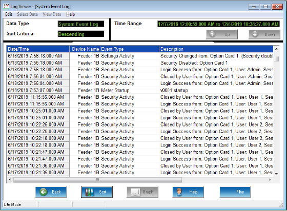
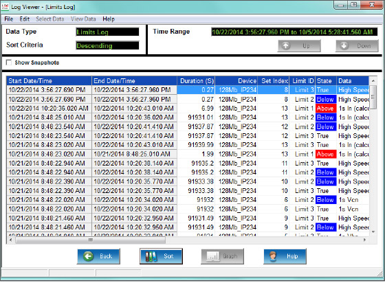
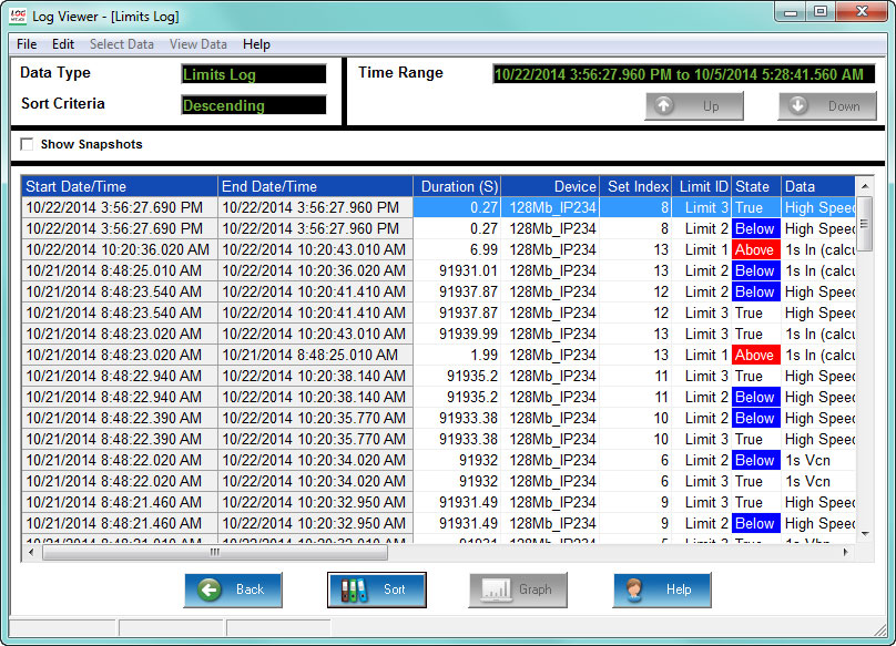
  • Detailed log information/status
  • Meter and diagnostic Information for meter applications and troubleshooting
Meter and diagnostic Information for meter applications and troubleshooting

The Multilin™ EPM 9900P is one of Multilin’s most advanced power quality meters and provides comprehensive perspective of energy usage; capture of power quality events and easy integration with support for multiple protocols to provide key decision making and monitoring information for critical energy circuits in utility substation or industrial applications.

EPM 9900P

High Performance Power Quality and Transient Recorder Meter

The Multilin™ EPM 9900P is one of Multilin’s most advanced power quality meters and provides comprehensive perspective of energy usage; capture of power quality events and easy integration with support for multiple protocols to provide key decision making and monitoring information for critical energy circuits in utility substation or industrial applications.

Features

Communications
  • Modbus, DNP 3.0, IEC 61850 (including high speed GOOSE messaging), SNMP, IEC 1588 PTPv2 and IEEE 37.118.2-2011
  • Standard Ethernet communications port with dual Ethernet capability
  • Port control to secure and disable services/ports
  • Easy system integration supporting up to 32 Modbus TCP/IP sockets per Ethernet port along with configurable Ethernet port services for security 
Measuring and Metering
  • 0.06% Energy Accuracy (ANSI 0.2%)
  • IEC 61000-4-30 Power Quality Class A Ed. 3 and EN50160 Reporting Support
  • Available 50MHz Transient Recorder (over 800,000 samples/cycle)
  • Phasor Measurement Unit (PMU) Capability
  • Harmonics up to the 511th order (Voltage,Current), 127th order in real time
  • Voltage Sag/Swell, Current Fault and Transient Recording
  • Up to 4 GB data logging

High Performance Power Quality and Transient Meter for Utility or Industrial Applications

Power generation / Grid automation / Industrial / Commercial data center

The EPM 9900P provides revenue accuracy for energy monitoring and high performance power quality analysis functions including harmonics, flicker and transient waveform capture. Power quality reporting data is collected in compliance with IEC 61000-4-30 Class A and EN 50160 international standards providing users a deep understanding in a variety of utility or industrial applications.

With up to 4GB of data logging, including 50 MHz transient capture, the EPM 9900P ensures that essential power quality data and events are captured, stored, and time synchronized allowing for comprehensive analysis of events. The EPM 9900P also supports a multitude of communications protocols such as Modbus, DNP3 and 61850 making it easy to integrate and retrieve data into a SCADA or data analysis system.

Application Example

Multifunction Metering & Power Quality Monitoring

The EPM 9900P can provide a total picture of power usage and power quality at different points within a power distribution network, allowing users to make power related decisions quickly and effectively.

EPM 9900P application example

Class A Power Quality Reporting

Extensive harmonics analysis capabilities Extensive harmonics analysis capabilities
Comprehensive Phasor visualization Comprehensive Phasor visualization
User-friendly reports illustrating PQ compliance User-friendly reports illustrating PQ compliance
Record and Analyze Waveform Fault and Transient Data

The EPM 9900P captures and stores comprehensive power quality information, including harmonics, sags, swells and transients providing a clear perspective and log of faults and disturbances to allow for detailed and extensive forensic engineering analysis. 

IEC 61000-4-30 Class A Ed.3 Power Quality Meter
  • Designed specifically to meet the rigorous IEC 61000-4-30 Class A Ed. 3 standard, the EPM 9900P measures and analyzes power quality metrics precisely. 
  • All reporting is available via the EN 50160 reporting format which can be further customized to meet the required application or regulatory needs.
IEC 61000-4-15 Class A Flicker Meter
  • Flicker compliant with the IEC 61000-4-15 Class A standard 
  • Operates on both 220 volt/50 Hz and 120 volt/60 Hz throughout standard test points
IEC 61000-4-7 Class A Harmonics and Interharmonics Analysis
  • View harmonic magnitudes to the 511th order for each voltage and current channel 
  • Harmonic magnitudes and phase angles in real time are resolved to the 127th order 
  • Obtain %THD, TDD, and K-Factor 
  • Conduct power quality analysis at the high end of the harmonic magnitude spectrum 
Phasor Analysis

The monitor reads a phase angle analysis between the voltage and current channels, allowing you to analyze efficiency and system integrity.

High-speed Voltage Reliability Measurements

The EPM 9900P meter provides industry leading voltage measurement.

  • Real time single cycle RMS measurements
  • Customizable high-speed readings – can be set from 2 to 20 cycles RMS
Set Limit Control

Programmable setpoints allowing a user to configure the meter to be used as a control device for many applications, such as:

  • Capacitor control
  • Load shedding
  • Automatic transfer schemes
  • Transformer monitoring & control
  • Redundant protection (not designed for primary over-current protection)
  • Many other control functions 
Alarm Notification

The EPM 9900P meter lets you set multiple programmable limits for any measured value, as well as those set up in a Boolean logic tree, and limits set up in the IEC 61850 protocol implementation. Users can be notified of alarm conditions via email.

16 Bit Waveform and Fault Recorder
  • Record up to 1024 samples per cycle; capture a transient at over 800,000 samples per cycle or at 50 MHz sampling speed
  • Voltage and current recording with pre and post-event analysis
  • Fault recording offers 8 times full scale capture capability
  • 16 bit A/D converter provides precise waveform resolution
  • Both hardware and software triggers are available
High-speed Status Input Triggers
  • Waveforms are recorded at time of status change
  • Input change and waveform recording are time-stamped to a 100 micro second resolution
  • Inputs and waveforms can be displayed together to time breakers and relays
Subcycle 50 MHz Transient Recorder (Software Option C)

A user can define log sizes within the meter. Thus the full memory can be allocated specifically to the desired function.

Independent ITIC/CBEMA Log Plotting
  • Quickly view total surges, sags, and average duration in the independent ITIC/CBEMA log
  • SEMI F47 graphing for power quality compliance in semiconductor industry 
Compatible Waveform Formats

Using GE Vernova Communicator software, the meter will provide all waveform data via COMTRADE and PQDIF compatible formats. This allows the waveform PQ and fault records to be read by most third-party waveform analysis software programs.

  • COMTRADE (common format for transient data exchange) is defined by IEEE Std C37.111
  • PQDIF (power quality data interchange format) is defined by IEEE Std 1159.3-2003

Record Phasor Measurement Unit (PMU) Data for Analysis

EPM 9900P PMU/Synchophasor Functionality

The EPM 9900P meter has been enhanced with Phasor Measurement Unit (PMU) functionality meeting the IEEE C37.118.1a-2014 standard. A PMU device measures time-synchronized, phasor (magnitude and phase angle of voltage and current) and related data from a specific location on the electrical grid. The data from multiple PMUs are transmitted to a phasor data concentrator (PDC), which aggregates and time-aligns the data for real time and post analysis.

Collection of Synchrophasor data is useful in applications such as: 

  • Aggregation of instantaneous, time synchronized voltage, current, and frequency at specific locations on the grid for easy greater wide-area system operator situational awareness
  • Determination of stress points of the utility transmission system
  • Detect and aid in restoration an islanded section of the grid after a storm or major outage disturbance
  • Collection and integration of PMU data for visualization in an Energy Management System (EMS). 
EPM 9900P Synchrophasor Features
  • Supports both P and M classes
  • Time sync standard: IRIG-B or IEEE 1588 PTPv2
  • Calculates individual voltage/current phasors, symmetrical components’ phasors, frequency, rate of change of frequency, the meter’s high-speed digital inputs, analog fundamental power, and displacement power factor
  • Data frame rates:
    • 50 Hz - 10/25/50 frames per second
    • 60 Hz - 10/12/15/20/30/60 frames per second
  • Data format: configurable float or integer, polar or rectangular
  • Support for up to two simultaneous clients with Ethernet or Fiber over Ethernet communication

Easy System Integration and Available IEC 61850 Solution

IEC 61850 Solution

Software options B and above offer an embedded IEC 61850 Protocol Server for seamless integration with substation automation and industrial 61850 applications.

  • The IEC 61850 Protocol Server allows up to 6 simultaneous MMS clients.
  • Either Ethernet port can be configured for IEC 61850 (only one port at a time can run IEC 61850)
  • GOOSE publisher/subscriber functionality is supported.
  • Buffered and unbuffered reports are supported for the following triggers: general meter interrogation, for example, the report is generated in response to a query; meter integrity, for example, the report is generated according to a programmed interval; and data change, for example, the report is generated due to a change in the contents of a dataset.
  • File transfer is supported
  • Embedded Web Protocol Server support is available for IEC 61850 CID file uploading, IEC 61850 Protocol Server status and for displaying incoming and outgoing GOOSE messages.
  • Multiple Logical Nodes, which map flicker, harmonics, digital inputs/outputs, limit state, voltage, current, energy and other data, are supported.
  • Waveform capture can be triggered by status input data inside GOOSE messages. The user can program up to 16 status inputs that will trigger a waveform capture when the information is received via a GOOSE message. The status inputs include digital inputs, limit states, and any other status input supported by the meter.
Unique GOOSE Cross Trigger
  • Fault-based cross trigger of waveform based on GOOSE message
  • Provides system-wide distribution fault analysis on an event
  • Timing better than 200 microseconds is typical
  • Many different circuits can be viewed after an event occurred
Intelligent Substation IEC 61850 Design

Flexible Communications Options

The EPM 9900P meter offers up to 6 simultaneous communication ports and multiple protocols to meet almost every need.

Hardware Features:
  • 2 optional RS485 ports speaking Modbus and/or DNP 3.0
  • USB front panel port
  • ANSI optical front panel port
  • 2 separately addressable Ethernet ports
  • Optional Fiber or RJ45 media on one Ethernet port
Ethernet Communication Port Capabilities
  • 2 Ethernet ports provide multiple simultaneous communication
  • Each port has separate MAC address and IP address
  • Supports Modbus TCP/IP, DNP 3.0 and IEC 61850
  • GOOSE messaging protocol supported for IEC 61850
  • Up to 32 Modbus TCP/IP sockets per Ethernet port
  • Highly secure port control to disable unneeded services and ports
  • Email Function - SMTP email to client on alarm
  • Precise Time Synchcronization - SNTP Time Sync protocol
  • File Transfer Protocol - High-speed file data transfer
  • Support for IEEE 1588 PTPv2 for critical time sync applications, e.g., synchrophasor systems.
  • IEEE C37.118.2 PMU communication
Industry-Leading DNP 3.0 Level 2 Plus – Complies with DNP Level 1 and Level 2 Certification Requirements 
  • Up to 136 measurements (64 Binary Inputs, 8 Binary Counters, 64 Analog Inputs) can be mapped to DNP static points
  • Up to 16 relays and 8 resets can be controlled through DNP
  • Report-by-exception processing (DNP Events) deadbands with unsolicited response for serial communication
  • 250 available events, in four event types (Binary Input Change, Frozen Counter, Counter Change, and Analog Change)
SNMP Protocol

SNMP protocol V1 and V2 are supported for managed device networks (i.e. Data center network applications) Features include:

  • Support for 40+measurements
  • Traps for limits, input change, and power quality
  • Cold start trap and authentication failure supported 
8 Built-in Digital High-speed Status Inputs 
  • Inputs automatically sense whether the circuit is externally wetted
  • If externally wetted, input up to 150 VDC is accepted
  • If internally wetted, the meter supplies the necessary voltage for the control application
VAUX Input
  • Neutral to ground or aux voltage readings
  • Synchronizing schemes, for example, obtaining the frequency, magnitude, and phase angle on both sides of a switch or between generator and bus voltage
EPM 9900P rear view

Multilin Meter Enclosure

meter enclosure

Expanding existing switchgear or installing new metering capability can be challenging due to space limitations, downtime and installation and equipment costs. GE Vernova’s Multilin Meter Enclosure is a pre-wired configured, economical solution for both retrofit expansions and small scale meter installations that allows the expansion of existing switchgear capability without expensive and time-consuming design.

When ordered as a meter option the enclosure provides a factory pre-wired, installation-ready metering solution that further drives energy cost savings, by enabling the measurement of key energy usage information along multiple metering points for new or existing systems. Ordering the enclosure is simple when selected as an option during meter configuration, ensuring correct pre-wired meter-compatible delivery.

Pre-Wired, Configured and Economical Solution for Retrofit and Small Metering Systems

Easy and Rapid Installation
  • Factory pre-wired, installation-ready GE Vernova metering solution eliminates wiring and associated errors for rapid installation
  • Extend metering capability with new systems and existing switchgear without system installation downtime
Cost-Effective Retrofit Solution
  • Save up to 200% versus the addition of a new switchgear cabinet
  • Compact footprint makes effective use of existing allocated space
  • Allows new installations or the expansion of existing switchgear capability without expensive, time-consuming designs, eliminating system downtime
Reliable and Compatible
  • Backed by a 10 year warranty
  • Simple meter option ordering ensures compatibility with GE Vernova EPM 9900P meters
  • Comprehensive factory testing of both meter and enclosure together
  • NEMA1 tested and UL/CUL certified 
Applications (New and Retrofit installations)
  • Utility/Indusrial Power Quality Studies
  • Healthcare Institutions
  • Government Buildings
  • Manufacturing
  • Educational Campuses
  • Data Centers
Meter Enclosure Assembly

The installation of the GE Vernova’s Multilin Meter Enclosure is simple, safe and eliminates downtime through simple mounting and wiring. The enclosure is UL/CUL certified and NEMA 1 rated making it ideal for indoor environments.

It is provided in two voltage configurations (120-240V and 277V) to ensure compatibility with customer installations. The standard equipment includes voltage fuses; a shorting block for current transformers; and a control power transformer for 277V power systems that are pre-wired and configured to ensure safety, quality and long-term reliability.

meter enclosure

Software Options

The EPM 9900P provides software options to meet specific power quality measurement functionality as well as logging, sampling and communications requirements.

The software options are also upgradeable after purchase/installation. This provides flexibility to expand functionality for future requirements or budgetary approval.

FEATUREABCDEF
Basic Measurements
Memory512 MB1GB4GB512 MB1GB4GB
Sampling Speed (samples/cycle)5121024102451210241024
50 MHz Transients    
IEC 61000-4-30 Class A Edition 3
IEC 61850 Server  
IEC 61850 GOOSE  
CyberSecurity   
Synchrophasor PMU   

Technical Specifications

INPUT VOLTAGE RANGE
  • (5-347)VAC, Line to Neutral
  • (10-600)VAC, Line to Line
VOLTAGE INPUT WITHSTAND CAPABILITY
  • Voltage Inputs isolated to 2500VAC
INPUT CURRENT RANGE
  • Programmable to any CT radio
  • Class 2: Nominal 1 A, with 2 times over range
  • Class 2: fault current recording to +/- 16 A peak
  • Class 20: Nominal 5 A, with 4 times over range
  • Class 20: fault current recording to +/- 80 A peak
CURRENT INPUT WITHSTAND CAPABILITY (AT 23 °C)
  • 100 Amps for 10 Seconds
  • 300 Amps for 3 Seconds
  • 500 Amps for 1 Second
BURDEN
  • Voltage Inputs: 0.072 VA/Phase Max at 600 Volts, 0.003W/Phase Max at 120 Volts
  • Current Inputs: 0.008 VA per Phase Max at 20 Amps
ISOLATION
  • All inputs to outputs are isolated to 2500 VAC
TEMPERATURE RATING
  • Operating Temperature: (-20 to +70)°C
  • Humidity: Up to 95% RH Non-condensing
  • Storage Temperature: (-30 to +80)°C
SENSING METHOD
  • Up to 1024 Samples per Cycle (Programmable)
  • 16 Bit A/D Resolution – Multiple Converters
  • True RMS
  • Constant CalibrationTM technology
  • Transients measured at 800,000 samples per cycle
ACCURACY RATING
  • ANSI C12.20 (Class 0.2) and IEC 62053-22 (Class 0.2S) Accuracy, 0.06% Energy measurement accuracy
  • Full accuracy specifications available in User Manual
  • Time clock: 3.5 ppm for -40 to +85°C - less than 10 seconds drift per month on crystal sync; 2.0 ppm Typical from 0 - +40°C - less than 6 seconds per month drift
UPDATE TIME
  • 1 Second — Revenue Accurate Readings
  • 1 Cycle — Faster updated readings
  • Customizable high-speed readings from 2 to 20 cycles RMS

Note: Please see product User Manual for comprehensive specifications.

CONTROL POWER REQUIREMENTS
  • HI Option: (100-240)VAC @50/60 Hz or (100-240)VDC
  • AC Option: (100-240)VAC @50/60 Hz
  • LD Option: (18-60)VDC (24-48 VDC Systems)
  • Burden: 25 VA Max
FREQUENCY RANGE
  • 45Hz–69.9Hz
COMMUNICATION FORMAT
  • Programmable parity and stop bits
  • Communication Protocols: Modbus TCP/IP, ASCII/RTU, DNP 3.0, IEC 61850 (Software Option B or C)
  • ANSI Optical Port
  • USB 1.1/2.0 Virtual COM Port
  • RJ45 Ethernet Port 10/100BaseT
  • Standard RJ45 Ethernet Port 10/100BaseT
  • Optional Serial RS485 Ports (Meter, I/O card)
  • Optional 2nd Ethernet port - RJ45 Ethernet or Fiber Optic
SHIPPING
  • Total shipping weight: approx. 6.5 lbs (2.9 kgs)
  • Shipping container dimensions: 16” x 15.5” x 11.5” (40.64 am x 39.37 cm x 29.21 cm)
COMPLIANCE
  • ANSI C12.20 (Class 0.2) and IEC 62053-22 (0.2S Class) Accuracy
  • ANSI C12.1 (Code for Electricity Metering)
  • ANSI C62.14 (Burst)
  • FCC Part 15, Subpart B, Class A
  • IEC 62053-23 Ed. 1
  • IEC 61000-4-2 - ESD
  • IEC 61000-4-3 - Radiant Immunity
  • IEC 61000-4-4 - Fast Transient
  • IEC 61000-4-5 - Surge Immunity
  • IEC 61000-4-6 - Conducted Immunity
  • IEC 61000-4-7 - Harmonics
  • IEC 61000-4-15 - Flicker Meter
  • IEC 61000-4-30 - Class A Ed. 3
  • IEC 61000-6-2 2005 (Immunity for Industrial Environments)
  • IEC 61000-6-4 2006 (Emissions Standards for Industrial Environments)
  • IEC 61850 Level A, Ed. 2 Certified
  • CISPR11 Ed. 5.1 (Conducted Emissions)
  • CISPR22 Class A
  • IEC 62052-11 2003- General
    Requirements
  • CE Marked
  • UL and cUL Listed