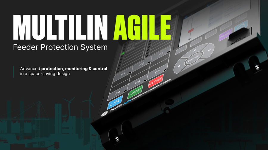
Multilin Agile
Compact Feeder Protection and Bay Controller

GE Vernova’s Multilin Agile Feeder Protection solution offers advanced protection, monitoring, and control for utilities, industrial plants, onshore and offshore renewable collectors, and more. Serving as primary or backup feeder protection, it is equipped with advanced communication options and extensive monitoring capabilities.
Applicable to distribution and industrial feeders, this powerful yet compact device features a graphical color display for presenting configurable Single Line Diagrams that enables bay monitoring and control. It also provides distribution feeder protection for the detection of faults on compensated networks, and load encroachment on heavily loaded lines.
Key benefits:
- Small footprint for easy retrofitting of aging infrastructure
- Intuitive graphical display for effective monitoring, communications, and troubleshooting
- Advanced functions addressing the challenges of renewable integration
- CyberSentry™ Advanced Cybersecurity to prevent unauthorized access and cyber attacks
- Draw-out design for simplified testing, commissioning, and maintenance
- Cost savings on engineering time and wiring
Multilin Agile
Compact Feeder Protection and Bay Controller
GE Vernova’s Multilin Agile Feeder Protection solution offers advanced protection, monitoring, and control for utilities, industrial plants, onshore and offshore renewable collectors, and more. Serving as primary or backup feeder protection, it is equipped with advanced communication options and extensive monitoring capabilities.
Applicable to distribution and industrial feeders, this powerful yet compact device features a graphical color display for presenting configurable Single Line Diagrams that enables bay monitoring and control. It also provides distribution feeder protection for the detection of faults on compensated networks, and load encroachment on heavily loaded lines.
Key benefits:
- Small footprint for easy retrofitting of aging infrastructure
- Intuitive graphical display for effective monitoring, communications, and troubleshooting
- Advanced functions addressing the challenges of renewable integration
- CyberSentry™ Advanced Cybersecurity to prevent unauthorized access and cyber attacks
- Draw-out design for simplified testing, commissioning, and maintenance
- Cost savings on engineering time and wiring
What is Multilin Agile?
Multilin Agile is a compact feeder protection and bay controller device with extensive protection, control, and communications capabilities. The design ensures that performance, sensitivity, customization, and flexibility are delivered along with minimized configuration and commissioning effort. The device is configured using software with few order code variants, providing standardization that mitigates the risk of mis-ordering, enables easy stocking, and reduces spare inventory.
Intuitive software and graphical display streamline and declutter the settings menu by hiding unnecessary elements. Default applications are pre-loaded and a simple configuration column readies the product for application from a single touchpoint for effective monitoring, communications, and troubleshooting.

The draw-out design permits fast extraction and insertion with inherent safety features to minimize risks associated with open-circuit CTs. The relay’s printed circuit boards have harsh environmental coating as the standard, to shield from contaminants such as moisture, salt mist, and atmospheric pollution, extending operational life.
Multilin Agile housed in a 30TE (6 inch) wide case supports integrated color graphical display. The device provides advanced functionality, including high-performance protection, extensive monitoring and control functions, redundant Ethernet communication, higher I/O density of up to 30 inputs / 25 outputs, and flexible configuration capabilities in a compact form factor and shallow depth of less than 155 mm behind panels.
In case a standard LCD text display is needed, please refer to P40 Agile Enhanced offering
Overview
Multilin Agile Feeder P14D Functional Block Diagram

ANSI® Device Numbers and Functions
| Device Number | Function |
|---|---|
| 21BL | Load encroachment supervision (Load blinders) |
| 24 | Volts per Hertz |
| 25 | Check Synchronising |
| 27 | Phase and Line Undervoltage |
| 27V | Positive Suquence Undervoltage |
| 27Q | UV Reactive Power |
| 27T | Timed Undervoltage |
| 32 | Phase Directional Power |
| 32N | Wattmetric Ground Fault |
| 37 | Undercurrent |
| 46 | Negative Sequence Overcurrent |
| 47 | Negative Sequence Overvoltage |
| 49 | Thermal Overload |
| 50/27 | Switch-on to Fault |
| 50 | Phase Definitive Time Overcurrent |
| 51 | Phase Inverse-Time Overcurrent |
| Device Number | Function |
|---|---|
| 52 | Breaker and Isolator Control |
| 52PD | Pole Discrepancy |
| 55 | Power Factor |
| 59 | Phase and Line Overvoltage |
| 59V | Positive Sequence Overvoltage |
| 67 | Directional Phase Overcurrent |
| 68 | Inrush Blocking |
| 79 | Autoreclose |
| 86 | Latching/Lockout Contacts |
| 21FL | Fault Locator |
| 46BC | Broken Conductor |
| 50BF | CB Failure |
| 50N/G | Neutral/Ground Definitive Time Overcurrent |
| 51N/G | Neutral/Ground IDMT Overcurrent |
| SEF | Sensitive Earth Fault |
| 51R | Voltage Restrained Overcurrent |
| Device Number | Function |
|---|---|
| 51V | Voltage Controlled Overcurrent |
| 67_2 | Directional Negative Sequence Overcurrent |
| 59N | Neutral Voltage Displacement |
| 67N | Directional Neutral/Ground Overcurrent |
| 81df/dt | Rate of Change Frequency |
| 81O | Overfrequency |
| 81U | Underfrequency |
| 81V | Undervoltage Blocking |
| 87G | Restricted Ground Fault (REF) |
| CLP | Cold Load Pick Up |
| CTS/VTS | CT and VT Supervision |
| DC Supply Monitoring | |
| Fast underfrequency | |
| Underfrequency Restoration | |
| TGFD | Transient Ground Fault Detection |
| THD | Hamonic Measurement/Protection |
| YN | Neutral Admittance |
Advanced Communications
Three communication ports are standard: a rear serial port providing remote communications, a front USB port, and a rear Ethernet for device configuration and management.
Two additional Ethernet ports can be ordered to achieve Ethernet communication redundancy.
Supported Communication Protocols Include:
- Modbus (RS485 serial or Ethernet)
- IEC 60870-5-103
- DNP 3.0 (RS485 serial or Ethernet)
- IEC 61850 Ed. 2 with concurrent serial connection
- Redundant Ethernet protocols PRP, HSR, and failover also available with dual RJ45 or dual fiber media
Flexible Hardware
- Space-saving 4U height with 6" (30TE) case size
- Wide choice of opto-isolated binary inputs and output relays
- Binary inputs ESI 48-4 EB2 compliant – avoids spurious pickup from induction on field wiring
- High density I/Os in various combinations depending on case size option
- Ungrouped binary inputs for trip circuit supervision
- Field upgradeable, avoiding costly hardware changes
- 6" (30TE) models can accommodate:
- 1 x RS485/IRIG-B interface
- Up to 3 x RJ45/fiber optic ports for single and redundant Ethernet plus additional engineering access
- From 11 to 30 binary inputs, and 9 to 25 relay outputs, depending on the order code
Simulation & Testing
To aid commissioning, a simulation feature is provided to test the relay’s functionality and response to programmed conditions, without the need for external AC voltage and current inputs. When placed in simulation mode, the relay suspends reading actual AC inputs, generates samples to represent the programmed phasors, and loads these samples into the memory to be processed by the relay. Normal (pre-fault), fault, and post-fault conditions can be simulated to exercise a variety of relay features. Other test operations, such as an LED lamp testing for each color, contact input states, and testing of output relays, are also possible.
Application Model Selection
| Model | Hardware Base | Intended Application | Case Model |
|---|---|---|---|
| P14NB | P14N | Non-directional feeder | 30TE |
| P14NL | P14N | Non-directional feeder with autoreclose | 30TE |
| P14NZ | P14N | Non-directional feeder with autoreclose and HIF** downed conductor | 20TE/30TE |
| P14DB | P14D | Directional feeder | 30TE |
| P14DL | P14D | Advanced directional feeder with autoreclose and check synchronising | 30TE |
| P14DZ | P14D | Advanced directional feeder with TGFD transient ground fault detection | 30TE |
| P94VB | P94V | Voltage and frequency | 30TE |
| P94VP | P94V | Voltage and frequency with autoreclose and check synchronising | 30TE |
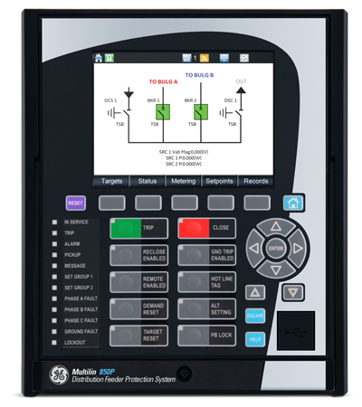
 Multilin Agile front panel interface – ANSI version
Intuitive User interface.
The front HMI hosts a fully graphical color screen. The front panel supports open, close, local/remote, and direct function key access, facilitating the control of connected switchgear and managing up to six controllable devices. These replace traditional hardwired control scheme switches and annunciation, saving on engineering time and wiring costs.
Sixteen tricolor LED lamps are available and freely configurable, in addition to four fixed-function LEDs that provide a cost-effective solution for annunciation.
Multiple languages are supported with easy switching between English and an additional language on the local display without uploading new firmware.
A USB front port allows ready access by field personnel laptops.
Intuitive Graphical Display

Phasor view for effective monitoring, commissioning & troubleshooting

Extensive recording for in-depth post-fault analysis

Accurate, real-time display of AC analog measurements

Enhanced bay visualization & control aided by single line diagram display
Product Explorer