MiCOM Agile P746
Centralized Busbar Differential Relay
The MiCOM Agile P746 provides complete protection for MV and HV busbar configurations with up to 2 zones plus a check zone, and up to 18 terminals. The MiCOM Agile P746 provides a centralized one box or three box architecture and is very simple to use. as it does not need to be deeply engineered and supports easy operation and maintenance of busbars.
The MiCOM Agile P746 protects busbar configurations at voltage levels up to extra-high voltage. Proven techniques and dynamic topology processing algorithms offer a combination of security, speed and sensitivity, with simple configuration for centralized architectures.
Key benefits:
- Tripping time is independent of substation topology and number of terminals
- User-friendly software tools for scheme monitoring
- Built-in CT saturation proof breaker failure protection
- Compatible with both conventional and NCITs
- No internal batteries in GE Vernova-branded models – removes a maintenance item and eases air-freight logistics
- Advanced binary inputs comply with the harshest norms for surge withstand, plus the ESI 48-4 EB2 standard. Spurious wiring pickup is eliminated without the use of interposing relays, external resistors or time delays. Battery/wiring faults, switching noise, and induction from long parallel circuits are tolerated without mis-operation
- Harsh environment protection extends the life of the product
What's New
Overview
- Typical operating time of 12 ms with high speed/high break contacts or 17 ms with standard contacts
- Phase segregated biased current differential high speed busbar protection
- Easy maintenance, operation and future expansion of the busbar supported
- Deploy in ring-bus/mesh corners, single busbars, sectionalized busbars, and one per bus in breaker and a half topologies
Key benefits:
- Use one box for schemes up to 6 feeders, and 3 boxes (one per phase) for larger schemes up to 18 terminals
- Interoperable with all classes of CT: IEEE, IEC, air-gapped, non-gapped, and CTs with moderate knee point voltage
- 10 integrated function keys, tri-color LEDs, and graphical programmable logic permit the creation of comprehensive schemes, tailored to your needs
- IEC 61850 redundant Ethernet with RSTP and IEC 62439 PRP and HSR – with HSR support for up to 50 nodes in a ring
Functional Block Diagram
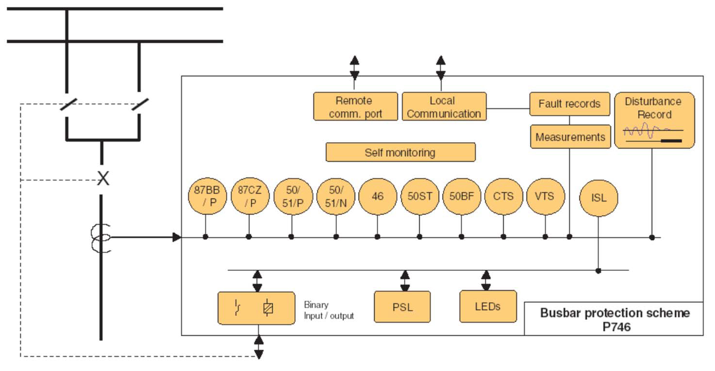
ANSI© Device Numbers and Functions
| Device Number | Function |
|---|---|
| 87BB | Bus Differential |
| 50 | Phase Definite Time Overcurrent |
| 51 | Phase Inverse-Time Overcurrent |
| 86 | Latching/Lockout Contacts |
| 50BF | CB Failure |
| 50N | Earth Fault Definite Time Overcurrent |
| 50ST | Short Zone Earth Fault |
| 51N | Neutral/Ground IDMT Overcurrent |
| VTS | VT Supervision |
| CTS | CT Supervision |
| PSL | Programmable Logic |
MiCOM S1 Agile
Key benefits:
- Powerful, free of charge, PC toolsuite
- Optimum management of the installed base, structured as per the substation topology
- Intuitive and versatile interface with file management facilities
- Logical structure based on substation, voltage level and bay
- Version control and cross-checking facilities for IED settings
- Real-time measurement visualization – MiCOM S1 Agile extends to all MiCOM Agile IEDs - including P847 PMU and busbar schemes
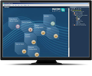
Engineering Tool Suite
S1 Agile is the truly universal PC tool for MiCOM Agile relay, assemble all tools in a palette for simple entry, with intuitive navigation via fewer mouse-clicks. No-longer are separate tools required for redundant Ethernet configuration, phasor measurement unit commissioning, busbar scheme operational dashboards, programmable curve profiles or automatic disturbance record extraction – applications are embedded. MiCOM S1 Agile supports all existing MiCOM, K-Series and Modulex, including a utility for automatic conversion of setting files from previous generations of numerical relays like K-series and MiCOM P20 to the latest P40 Agile models.
To move to the future, with no loss of functionality, no loss of device support, and full compatibility with your installed base and system architecture – request a copy of S1 Agile with the contact form link below.
Key features in the MiCOM S1 family:
- GE Vernova’s integrated engineering tool that provides users with access to automation IED configuration and record data
- Integrated configuration and monitoring features
- Send and extract setting files
- Event and disturbance record extraction and analysis
MiCOM S1 Agile software request
To receive the MiCOM S1 Agile, please use our Contact form. This will also ensure that you are kept up-to-date with the latest enhancements, including updates and bug fixes.
P746 Remote HMI PC Application Software
Agile P746 remote PC HMI provides the following features:
- P746 Remote HMI allows the user to display the MiCOM Agile P746 measured analogue quantities and DDB (digital data bus) status information dynamically via the user defined busbar topology
- Available in English, French, German, Spanish, Chinese and Russian
Please use our contact form to request the software.
Refurbishment Solutions
Refurbishment Solutions – “If It’s Blue Think to Renew”
GE Vernova’s latest MiCOM P746 model offers an ideal path to refurbish an older installed base of MiCOM P746 relays. Whether those older products were initially sold as GE VERNOVA or AREVA-branded products, newer models retain pin-pin refurbishment capability. Advantageously, users can benefit from the advancements made in protection, control, communications, hardware and cybersecurity that have taken place in the intervening years. The new P40 retains form, fit and function compatibility but delivers the latest platform and software ready for today’s environment, and for future-proofed application for the decades ahead.
Pin-Pin Upgrade Methodology:
- Take the order code (CORTEC) of the older relay being removed, typically a blue case relay
- Translate to today’s latest GE Vernova MiCOM model, adding Ethernet options if required
- Order the new P40 relay
- Extract settings and logic, use S1 Agile toolsuite to convert settings
- Detach the terminal blocks from old relay, leaving wiring attached / detach terminal blocks from the new.
- Carefully examine the terminal blocks to see that no physical damage has occurred since installation
- Mount new relay. Old relay blocks fit straight onto the new relay - safer, less wiring to reconnect.
- It is recommended to apply rated current and voltage to the relay CT/VT inputs during secondary injection testing to check the continuity of the CT/VT terminal block connections to the relay.
- Download converted files
- Test, return circuit to service with only minutes of downtime
Contact us for advice and support